Fig. A
Fig. C
Fig. E
6
Fig. B
Fig. D
Fig. F
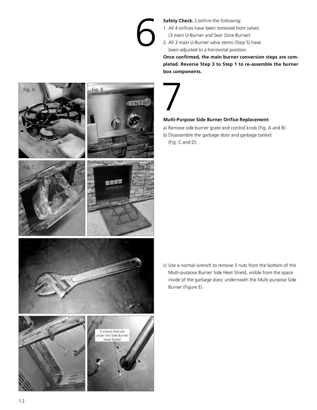
3 screws that are
under the Side Burner
Heat Shield
Safety Check. Confirm the following:
1.All 4 orifices have been removed from valves (3 main
2.All 3 main
Once confirmed, the main burner conversion steps are com- pleted. Reverse Step 3 to Step 1 to
7
a)Remove side burner grate and control knob (Fig. A and B).
b)Disassemble the garbage door and garbage basket (Fig. C and D).
c)Use a normal wrench to remove 3 nuts from the bottom of the
1 2
