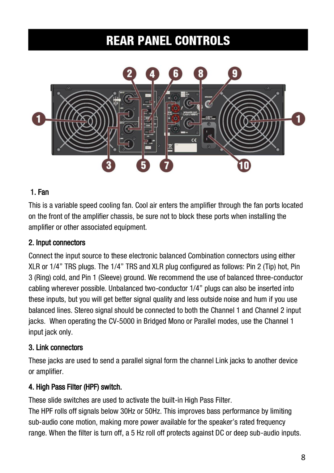
Cerwin-Vega CV-5000 user manual Rear Panel Controls, Fan, Input connectors, Link connectors

Models: CV-5000

1 19
Download 19 pages 4.15 Kb
Page 8
Image 8

REAR PANEL CONTROLS

1. Fan

This is a variable speed cooling fan. Cool air enters the amplifier through the fan ports located on the front of the amplifier chassis, be sure not to block these ports when installing the amplifier or other associated equipment.

2. Input connectors

Connect the input source to these electronic balanced Combination connectors using either XLR or 1/4” TRS plugs. The 1/4” TRS and XLR plug configured as follows: Pin 2 (Tip) hot, Pin 3 (Ring) cold, and Pin 1 (Sleeve) ground. We recommend the use of balanced three-conductor cabling wherever possible. Unbalanced two-conductor 1/4” plugs can also be inserted into these inputs, but you will get better signal quality and less outside noise and hum if you use balanced lines. Stereo signal should be connected to both the Channel 1 and Channel 2 input jacks. When operating the CV-5000 in Bridged Mono or Parallel modes, use the Channel 1 input jack only.

3. Link connectors

These jacks are used to send a parallel signal form the channel Link jacks to another device or amplifier.

4. High Pass Filter (HPF) switch.

These slide switches are used to activate the built-in High Pass Filter.

The HPF rolls off signals below 30Hz or 50Hz. This improves bass performance by limiting sub-audio cone motion, making more power available for the speaker’s rated frequency range. When the filter is turn off, a 5 Hz roll off protects against DC or deep sub-audio inputs.

8

Page 8
Image 8
Cerwin-Vega CV-5000 user manual Rear Panel Controls, Fan, Input connectors, Link connectors, High Pass Filter HPF switch