Connect the Gas Line
Gas access holes are provided on both sides of the firebox.
Check gas valve type. Use only the gas type indicated on the gas log rating plate. If the gas listed on the plate is not your type of gas supply, DO NOT INSTALL. Con- tact your Dealer for the proper model.
Always use an external regulator for all LP fireboxes to reduce the supply tank pressure to a maximum 14" w.c. This is in addition to the regulator fitted to the
WARNING: Connection directly to an un- regulated LP tank can cause an explosion.
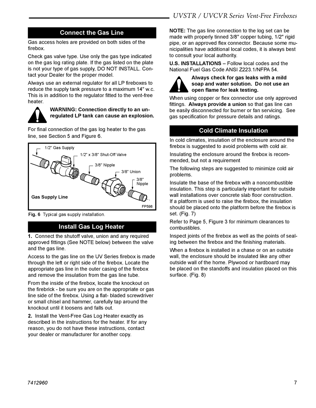
For final connection of the gas log heater to the gas line, see Section 5 and Figure 6.
| 1/2" Gas Supply |
| 1/2" x 3/8" |
| 3/8" Nipple |
| 3/8" Union |
| 3/8" |
| Nipple |
Gas Supply Line | |
| FP598 |
Fig. 6 | Typical gas supply installation. |
Install Gas Log Heater
1.Connect the shutoff valve, union and any required approved fittings (See NOTE below) between the valve and the gas line.
Access to the gas line on the UV Series firebox is made through the left or right side of the firebox. Locate the appropriate gas line in the outer casing of the firebox and remove the insulation from the gas line tube.
From the inside of the firebox, locate the knockout on the firebrick - be sure you are on the appropriate or gas line side of the firebox. Using a flat- bladed screwdriver or small chisel and hammer, carefully tap around the knockout until it loosens and falls out.
2.Install the
UVSTR / UVCVR Series Vent-Free Fireboxes
NOTE: The gas line connection to the log set can be made with properly tinned 3/8" copper tubing, 1/2" rigid pipe, or an approved flex connector. Because some mu- nicipalities have additional local codes, it is always best to consult your local authority.
U.S. INSTALLATIONS – Follow local codes and the National Fuel Gas Code ANSI Z223.1/NFPA 54.
Always check for gas leaks with a mild soap and water solution. Do not use an open flame for leak testing.
When using copper or flex connector use only approved fittings. Always provide a union so that gas line can be easily disconnected for burner or fan servicing. See gas specification for pressure details and ratings.
Cold Climate Insulation
In cold climates, insulation of the enclosure around the firebox is suggested to avoid problems with cold air.
Insulating the enclosure around the firebox is recom- mended, but not a requirement
The following steps are suggested to minimize cold air problems.
Insulate the base of the firebox with a noncombustible insulation. This step is particularly important for outside wall installations over concrete slab floor construction. If a platform is used to raise the firebox, the insulation should be placed onto the platform before the firebox is set. (Fig. 7)
Refer to Page 5, Figure 3 for minimum clearances to combustibles.
Inspect joints of the firebox as well as the points of seal- ing between the firebox and the finishing materials.
When a firebox is installed in a chase or on an outside wall, the enclosure should be insulated like any other outside wall of the home. Plywood or hardboard may be placed on the standoffs and insulation placed on this surface. (Fig. 8)
7412960 | 7 |