CFM Corporation Model 7000N Connecting to Natural Gas, Installation for Natural GAS

Models: 7000

1 29
Download 29 pages 22.27 Kb
Page 21
Image 21

Model 7000N • Connecting to Natural Gas

(for specially equipped natural-gas grills only)

DANGER: EXPLOSIVE AND FLAMMABLE! If the appliance is for connection to

natural gas, the gas connections should be made by a qualified installer or a licensed plumber. The gas-supply line must not be installed by the consumer.

The valve-orifices and fuel supply hose sys- tem necessary for use with natural gas is differ- ent than the system required for L.P. gas. Modification to the burner valve/orifices allow the use of natural gas. An L.P. cylinder is not needed.

A quick-connect coupling sleeve with 3/8” female end is provided. Install the connector socket at the pipe end, after the shut-off valve. This must be installed where the grill will be in use.

It is important to observe the safety guidelines for choosing a safe location. The gas supply must be shut off prior to installation of the quick con- nector socket. Use only a matching factory authorized quick-connect plug with the quick-con- nect socket.

Natural-gas units are equipped with a 12-foot- long quick-connect fuel hose in place of the short- er hose/regulator attached to the burner valve.

WARNING: Do not use liquid propane (L.P.) gas in an appliance designed for nat- ural gas. Use only natural gas in an appli- ance designed for natural gas.

INSTALLATION FOR NATURAL GAS

The maximum inlet supply pressure is 11.0" w.c. for propane gas and 7.0" w.c. for natural gas.

The specified supply pressure is 11.0" w.c. for propane gas and 7.0" wc. for natural gas.

The piping system should be installed by a qualified service technician in accordance with the National Fuel Gas Code (NFPA 54/ANSI

Z223.1) in the U.S.A., including:

1.The appliance and its individual shut-off valve must be disconnected from the gas-sup- ply piping system during any pressure testing of that system at test pressures in excess of 1/2 psi (3.5 kPa).

2.The appliance must be isolated from the
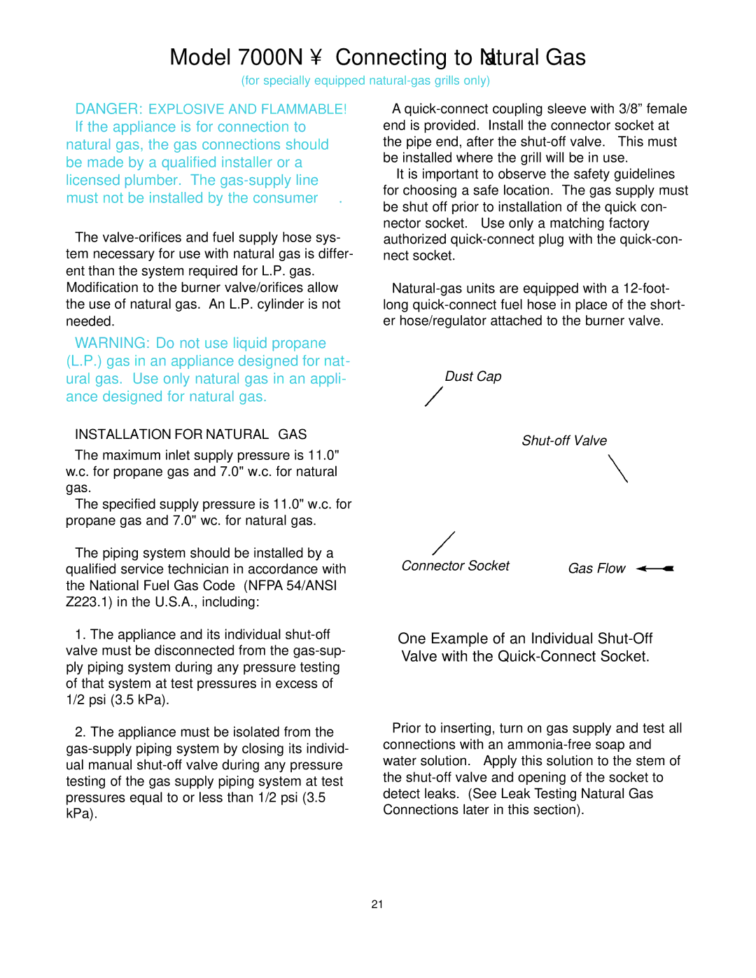
 gas-supply piping system by closing its individ- ual manual shut-off valve during any pressure testing of the gas supply piping system at test pressures equal to or less than 1/2 psi (3.5 kPa).

Dust Cap

Shut-off Valve

Connector Socket


Gas Flow


One Example of an Individual Shut-Off Valve with the Quick-Connect Socket.

Prior to inserting, turn on gas supply and test all connections with an ammonia-free soap and water solution. Apply this solution to the stem of the shut-off valve and opening of the socket to detect leaks. (See Leak Testing Natural Gas Connections later in this section).

21

Page 21
Image 21
CFM Corporation owner manual Model 7000N Connecting to Natural Gas, Installation for Natural GAS