Inspire Electric Fireplace
Fireplace Assembly
Unpack the Appliance
The Inspire Electric Heater is supplied in two (2) car- tons. All instructions should be read before beginning installation.
Carton 1 contents
1, Electric heater main body
1, Remote control handset with battery 1, Mounting hanger
1, Mounting hardware kit [#12 x 1/2” long screws (6), wall anchors (6), #8 x 1/4” short screws (4)]
1, Installation instructions 1, Pebble pack
2, Insert panels
Carton 2 contents
1, Trim assembly w/ six (6) magnets
Appliance Mounting
The heater must be mounted to a suitable wall using the mounting hanger provided. Consider the minimum clearance dimensions referenced on Page 3 and 4 for the mounting location. The following steps are for one method that can be used at your own risk. A helper is recommended.
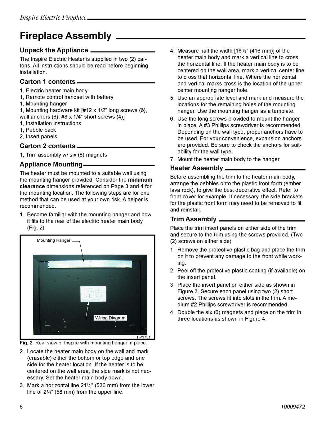
1.Become familiar with the mounting hanger and how it fits to the rear of the electric heater main body. (Fig. 2)
Mounting Hanger
Wiring Diagram
FP1731
Fig. 2 Rear view of Inspire with mounting hanger in place.
2.Locate the heater main body on the wall and mark (erasable) either the bottom or top edge and one side for the heater location. If the heater is to be centered on the wall area, the side mark is not nec- essary. Set the heater main body down.
3.Mark a horizontal line 21¹⁄₈” (536 mm) from the lower line or 2¹⁄₄” (58 mm) from the upper line.
4.Measure half the width [16³⁄₈” (416 mm)] of the heater main body and mark a vertical line to cross the horizontal line. If the heater main body is to be centered on the wall area, mark a vertical center line to cross that horizontal line. Where the horizontal and vertical marks cross is the location of the upper center mounting hanger hole.
5.Use an appropriate level and mark and measure the locations for the remaining holes of the mounting hanger. Use the mounting hanger as a template.
6.Use the long screws provided to mount the hanger in place. A #3 Phillips screwdriver is recommended. Depending on the wall type, proper anchors have to be used. For your convenience, expansion anchors are provided. Be sure to check the anchors for suit- ability for the wall type.
7.Mount the heater main body to the hanger.
Heater Assembly
Before assembling the trim to the heater main body, arrange the pebbles onto the plastic front form (ember lava rock), to give the best decorative effect. Refer to front cover for example. If necessary, the side brackets for the plastic front form may need to be removed to fit and reinstall.
Trim Assembly
Place the trim insert panels on either side of the trim and secure to the trim using the screws provided. (Two
(2) screws on either side)
1.Remove the protective plastic bag and place the trim on it to prevent any damage to the front while work- ing.
2.Peel off the protective plastic coating (if available) on the insert panel.
3.Place the insert panel on either side as shown in Figure 3. Secure each panel using two (2) short screws. The screws fit into slots in the trim. A me- dium #2 Phillips screwdriver is recommended.
4.Double the six (6) magnets and place on the trim in three locations as shown in Figure 4.
6 | 10009472 |