Expanding the 3308:
CATV/Ant
Model 3308
Model 3308 | Model 3308 |
Up to 64 TV outlets
You may connect up to 8 more 3308s to the outputs of a ‘master’ 3308, for a total of 64 TV outlets. The longest recommended coax run is 150 feet (includes coax from master to secondary unit and from secondary unit to TV).
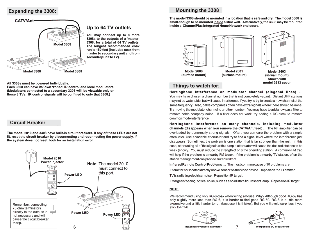
Mounting the 3308
The model 3308 should be mounted in a location that is safe and dry. The model 3308 is small enough to be mounted inside a stud wall. Alternatively, the 3308 may be mounted inside a ChannelPlus Integrated Home Network enclosure.
Model 2600 | Model 2601 | Model 2603 |
(surface mount) | (surface mount) | |
|
| Shown with |
All 3308s must be powered individually.
Each 3308 can have its’ own ‘zoned’ IR control and local modulators. (Modulators connected to a secondary 3308 will be viewable only on those 8 TVs. IR control signals will be confined to only that 3308.)
Circuit Breaker
The model 2010 and 3308 have
model 2613 cover |
Things to watch for:
Herringbone interference on modulator channel (diagonal lines) ...
You may have chosen a channel number that is not completely vacant. Distant UHF stations may not be watchable, but will cause interference if you try to try to create a new channel at the same frequency. Also, cable companies often have extra signals where there should be none. Try moving the modulator channel to another number. You may have to add a low pass filter to remove cable company noise. If a filter does not work, try adding a
Herringbone interference on many channels, including modulator channels (disappears when you remove the CATV/Ant feed) … The RF amplifier can be
overloaded by abnormally strong signals. Often, you can cure the problem with a simple attenuator. Use a variable attenuator and try to find a signal level where the interference just disappears. Sometimes, the problem is one station that is far stronger than the rest. In this case, attenuating all of the signals with a simple attenuator will cause the desired stations to be weak (snowy). You must reduce the strength of only the offending station. A common FM trap will help if the problem is a nearby FM tower. If the problem is a nearby TV station, often the
Model 2010
Power Injector
VIDEO SYSTEM
POWER 15VDC
Power LED
IR
EMITTERS
SYSTEM POWER
FROM
MODULATOR
Note: The model 2010 must connect to this port.
station management can provide suitable filters.
Infrared Remote Control Problems … The most common cause of IR problems are:
IR emitter not located directly above sensor on the video device. Reposition the IR emitter
TV is radiating electrical noise. Reposition IR target.
IR target is ‘seeing’ optical noise, such as a solid state flourescent lamp. Reposition IR target.
NOTE:
Remember, connecting 75 ohm terminators directly to the outputs is
Power LED
TARGET
We recommend using only
not necessary and will cause the circuit breaker to trip.
Power LED LED
EMITTER
POWER
TO
TV
6
Inexpensive variable attenuator | 7 | Inexpensive DC block for RF |
|