Setting the Starting Address
If this is your first time addressing a fixture using the
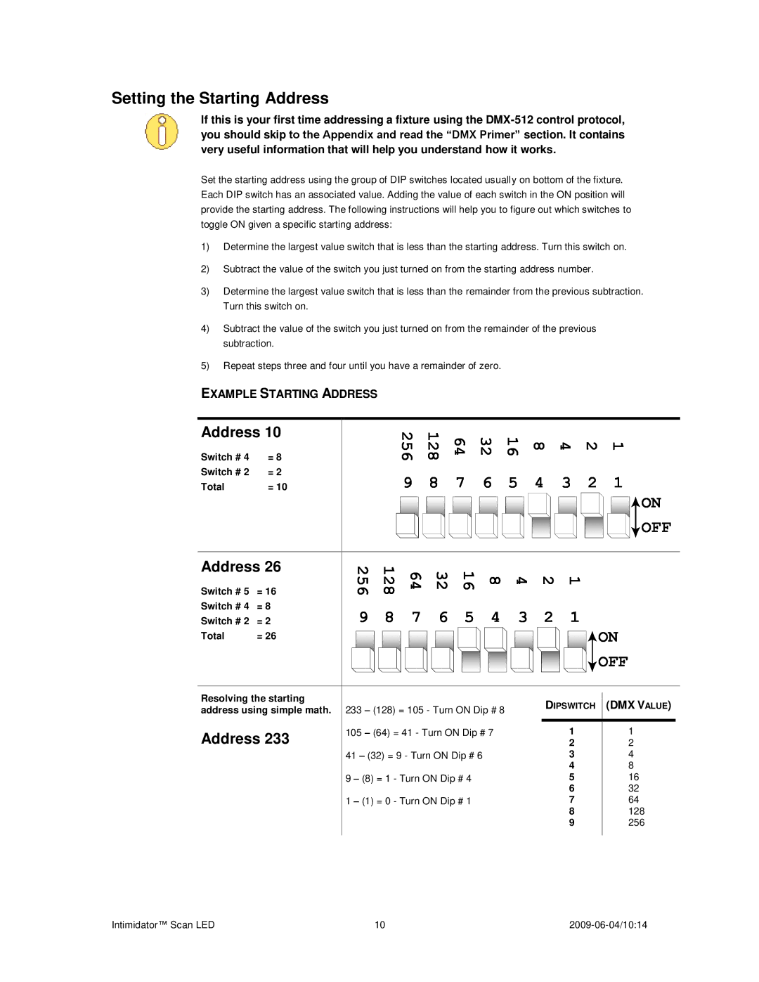
Set the starting address using the group of DIP switches located usually on bottom of the fixture. Each DIP switch has an associated value. Adding the value of each switch in the ON position will provide the starting address. The following instructions will help you to figure out which switches to toggle ON given a specific starting address:
1)Determine the largest value switch that is less than the starting address. Turn this switch on.
2)Subtract the value of the switch you just turned on from the starting address number.
3)Determine the largest value switch that is less than the remainder from the previous subtraction. Turn this switch on.
4)Subtract the value of the switch you just turned on from the remainder of the previous subtraction.
5)Repeat steps three and four until you have a remainder of zero.
EXAMPLE STARTING ADDRESS
Address 10
Switch # 4 | = 8 |
Switch # 2 | = 2 |
Total | = 10 |
Address 26
Switch # 5 = 16
Switch # 4 = 8
Switch # 2 = 2
Total | = 26 |
Resolving the starting address using simple math.
Address 233
|
| 256 | 128 | 64 | 32 | 16 | 8 | 4 | 2 | 1 |
|
| 9 | 8 | 7 | 6 | 5 | 4 | 3 | 2 | 1 |
|
|
|
|
|
|
|
|
|
| ON |
|
|
|
|
|
|
|
|
|
| OFF |
256 | 128 | 64 | 32 | 16 | 8 | 4 | 2 | 1 |
|
|
9 | 8 | 7 | 6 | 5 | 4 | 3 | 2 | 1 |
|
|
|
|
|
|
|
|
|
|
| ON | |
|
|
|
|
|
|
|
|
| OFF | |
233 – (128) = 105 - Turn ON Dip # 8 |
| DIPSWITCH (DMX VALUE) | ||||||||
|
|
|
|
| ||||||
105 – (64) = 41 - Turn ON Dip # 7 |
|
| 1 |
| 1 | |||||
|
|
|
|
|
|
|
| 2 |
| 2 |
41 – (32) = 9 - Turn ON Dip # 6 |
|
| 3 |
| 4 | |||||
|
|
|
|
|
|
|
| 4 |
| 8 |
9 – (8) = 1 - Turn ON Dip # 4 |
|
|
| 5 |
| 16 | ||||
|
|
|
|
|
|
|
| 6 |
| 32 |
1 – (1) = 0 - Turn ON Dip # 1 |
|
|
| 7 |
| 64 | ||||
|
|
|
|
|
|
|
| 8 |
| 128 |
|
|
|
|
|
|
|
| 9 |
| 256 |
Intimidator™ Scan LED | 10 |