3- PIN TO 5- PIN CONVERSION CHART
Note! If you use a controller with a 5 pin DMX output connector, you will need to use a 5 pin to 3 pin adapter. CHAUVET Model No: DMX5M, or DMX5F.
The chart below details a proper cable conversion:
3PIN TO 5 PIN CONVERSION CHART
Conductor | 3 Pin Female (output) | 5 Pin Male (Input) |
|
|
|
Ground/Shield | Pin 1 | Pin 1 |
|
|
|
Data ( - ) signal | Pin 2 | Pin 2 |
Data ( + ) signal | Pin 3 | Pin 3 |
Do not use |
| Do not use |
Do not use |
| Do not use |
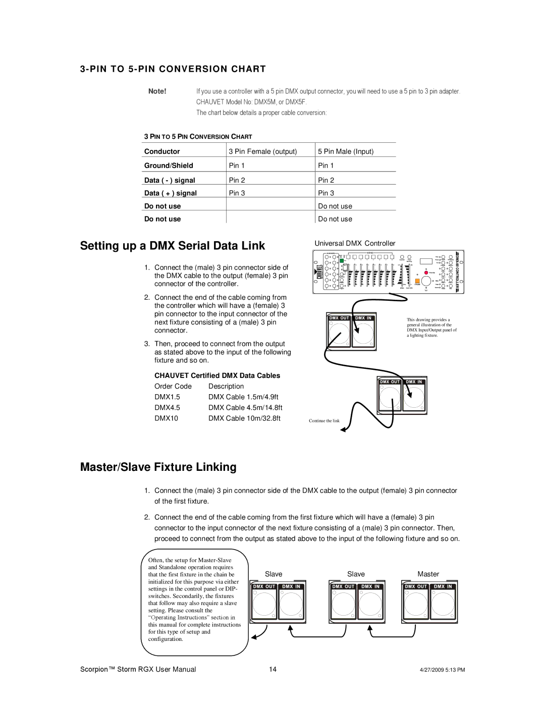
Setting up a DMX Serial Data Link
Universal DMX Controller
1. Connect the (male) 3 pin connector side of the DMX cable to the output (female) 3 pin connector of the controller.
2.Connect the end of the cable coming from the controller which will have a (female) 3 pin connector to the input connector of the
next fixture consisting of a (male) 3 pin connector.
3. Then, proceed to connect from the output as stated above to the input of the following fixture and so on.
CHAUVET Certified DMX Data Cables |
| |
Order Code | Description |
|
DMX1.5 | DMX Cable 1.5m/4.9ft |
|
DMX4.5 | DMX Cable 4.5m/14.8ft |
|
DMX10 | DMX Cable 10m/32.8ft | Continue the link |
This drawing provides a general illustration of the DMX Input/Output panel of a lighting fixture.
Master/Slave Fixture Linking
1.Connect the (male) 3 pin connector side of the DMX cable to the output (female) 3 pin connector of the first fixture.
2.Connect the end of the cable coming from the first fixture which will have a (female) 3 pin connector to the input connector of the next fixture consisting of a (male) 3 pin connector. Then, proceed to connect from the output as stated above to the input of the following fixture and so on.
Often, the setup for
for this type of setup and configuration.
Slave |
Slave |
Master |
Scorpion™ Storm RGX User Manual | 14 | 4/27/2009 5:13 PM |