Manuals
/
Chauvet
/
Household Appliance
/
Indoor Furnishings
Chauvet
Vue III Setting up a DMX Serial Data Link, Cable Connectors, PINTO 5-PINCONVERSION CHART
Models:
Vue III
1
8
17
17
Download
17 pages
15.82 Kb
5
6
7
8
9
10
11
12
Troubleshooting
Specifications
PINTO 5-PINCONVERSION CHART
Maintenance
Setup
Connector
What is
Safety
User Serviceable
Features
Page 8
Image 8
Page 7
Page 9
Page 8
Image 8
Page 7
Page 9
Contents
115V/230V Switch
User Serviceable
Ok on Dimmer
Outdoor OK
TABLE OF CONTENTS
3. SETUP
1. BEFORE YOU BEGIN
2. INTRODUCTION
What is included
AC Power
1.BEFORE YOU BEGIN
Unpacking Instructions
Safety Instructions
Features
2.INTRODUCTION
DMX Channel Summary
Additional Features
Product Overview
Tilt Adjustment Knob Dipswitches Sound
Sensitivity Knob Microphone Power Output
Connector
3. SETUP
Fuse Replacement
Fixture Linking
Data Cabling
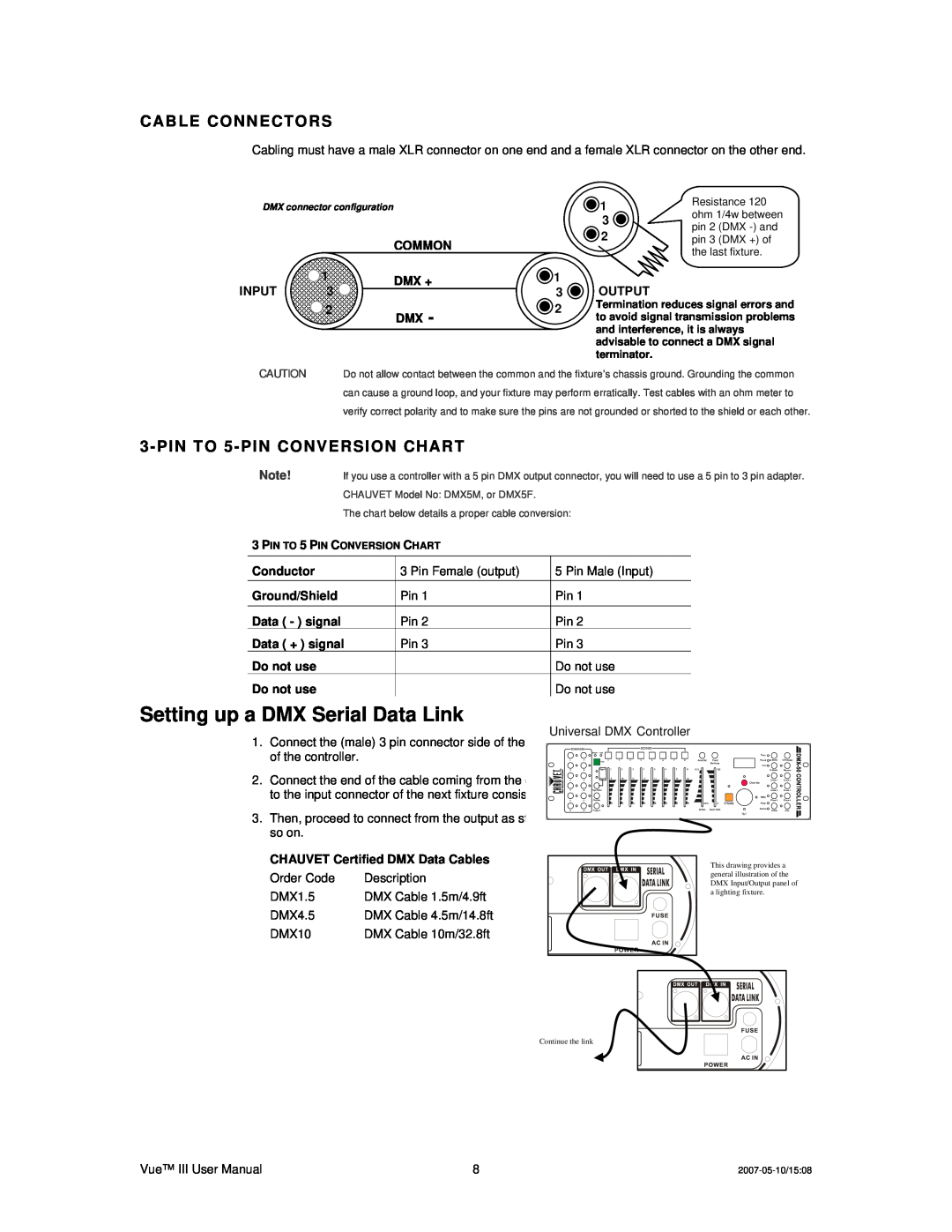
Setting up a DMX Serial Data Link
CABLE CONNECTORS
3-PINTO 5-PINCONVERSION CHART
The chart below details a proper cable conversion
Stand-Alone/Master/SlaveFixture Linking
Mounting
ORIENTATION
RIGGING
4.OPERATING INSTRUCTIONS
Operation
Master/Slave Mode Master Sound, Master Auto
DMX Mode
DMX Channel Values
Control/Operating Mode
Cluster
Cluster
LED Cluster Diagram
LED Cluster Values
ON OFF
DMX QUICK REFERENCE CHART
DMX Address Quick Reference Chart
General Troubleshooting
Applies to
General Maintenance
5.APPENDIX
Technical Support
DMX Primer
Returns Procedure
Technical Specifications
Claims
WEIGHT & DIMENSIONS
Top
Page
Image
Contents