Instructions for Putting into Use
Read the ENTIRE IMPORTANT SAFETY INFORMATION section at the beginning of this manual including all text under subheadings therein before set up or use of this product.
Note: For additional information regarding the parts listed in the following pages, refer to the Assembly Diagram near the end of this manual.
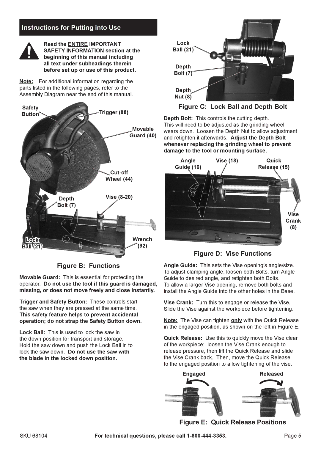
Safety | Trigger (88) |
Button |
Movable
Guard (40)
![]() Cut-off
Cut-off
Wheel (44)
Depth | Vise |
Bolt (7) |
|
Lock | Wrench |
Ball (21) | (92) |
Figure B: Functions
Movable Guard: This is essential for protecting the operator. Do not use the tool if this guard is damaged, missing, or does not move freely and close instantly.
Trigger and Safety Button: These controls start the saw when they are pressed at the same time.
This safety feature helps to prevent accidental operation; do not strap the Safety Button down.
Lock Ball: This is used to lock the saw in the down position for transport and storage. Hold the saw down and push the Lock Ball in to lock the saw down. Do not use the saw with the blade in the locked down position.
Lock
Ball (21)
Depth
Bolt (7)
Depth
Nut (8)
Figure C: Lock Ball and Depth Bolt
Depth Bolt: This controls the cutting depth.
This will need to be adjusted as the grinding wheel wears down. Loosen the Depth Nut to allow adjustment and retighten it afterwards. Adjust the Depth Bolt whenever replacing the grinding wheel to prevent damage to the tool or mounting surface.
Angle | Vise (18) | Quick |
Guide (16) |
| Release (15) |
Vise
Crank
(8)
Figure D: Vise Functions
Angle Guide: This sets the Vise opening′s angle/size. To adjust clamping angle, loosen both Bolts, turn Angle Guide to desired angle, and retighten both Bolts.
To allow a larger Vise opening, remove both bolts and install the Angle Guide into the other holes in the Base.
Vise Crank: Turn this to engage or release the Vise. Slide the Vise against the workpiece before tightening.
Note: The Vise can tighten only with the Quick Release in the engaged position, as shown on the left in Figure E.
Quick Release: Use this to quickly move the Vise clear
of the workpiece: loosen the Vise Crank enough to release pressure, then lift the Quick Release and slide the Vise Crank back. Then, move the Quick Release to the engaged position to allow tightening of the vise.
EngagedReleased
Figure E: Quick Release Positions
SKU 68104 | For technical questions, please call | Page 5 |