SAFETY
SETUP
OPERATION
MAINTENANCE
Operating Instructions
Read the ENTIRE IMPORTANT SAFETY INFORMATION section at the beginning of this manual including all text under subheadings therein before set up or use of this product.
Tool Set Up
TO PREVENT SERIOUS INJURY FROM ACCIDENTAL OPERATION:
Turn the Power Switch of the tool to its “OFF” position, remove the Safety Lock and unplug the tool from its electrical outlet before assembling or making any adjustments to the tool.
TO PREVENT SERIOUS INJURY:
DO NOT OPERATE WITH ANY GUARD DISABLED, DAMAGED, OR REMOVED.
Moving guards must move freely and close instantly.
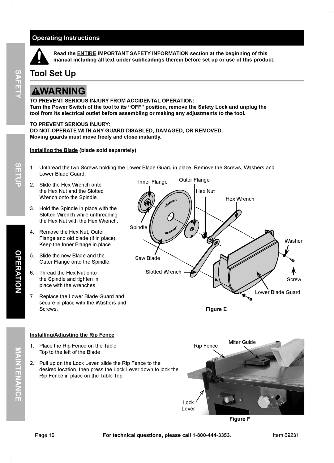
Installing the Blade (blade sold separately)
1.Unthread the two Screws holding the Lower Blade Guard in place. Remove the Screws, Washers and Lower Blade Guard.
2. | Slide the Hex Wrench onto | Inner Flange | Outer Flange |
|
|
| |||
|
|
| ||
| the Hex Nut and the Slotted |
| Hex Nut |
|
| Wrench onto the Spindle. |
|
| Hex Wrench |
3. | Hold the Spindle in place with the |
|
|
|
| Slotted Wrench while unthreading |
|
|
|
| the Hex Nut with the Hex Wrench. | Spindle |
|
|
4. | Remove the Hex Nut, Outer |
|
| |
|
|
| ||
| Flange and old blade (if in place). |
|
| Washer |
| Keep the Inner Flange in place. |
|
| |
|
|
|
| |
5. | Slide the new Blade and the | Saw Blade |
|
|
| Outer Flange onto the Spindle. |
|
| |
|
|
|
| |
6. | Thread the Hex Nut onto | Slotted Wrench |
| |
| the Spindle and tighten in |
|
| Screw |
| place with the wrenches. |
|
|
|
7. | Replace the Lower Blade Guard and |
|
| Lower Blade Guard |
|
|
| ||
| secure in place with the Washers and |
|
|
|
| Screws. |
| Figure E | |
Installing/Adjusting the Rip Fence |
|
|
| |
1. | Place the Rip Fence on the Table |
| Rip Fence | Miter Guide |
|
| |||
| Top to the left of the Blade. |
|
|
|
2.Pull up on the Lock Lever, slide the Rip Fence to the desired location, then press the Lock Lever down to lock the Rip Fence in place on the Table Top.
Lock ![]()
Lever
Figure F
Page 10 | For technical questions, please call | Item 69231 |