Installation Instructions |
| ||
2. | Select spacers: |
|
|
| • If mounting holes are flush with back of display, |
|
|
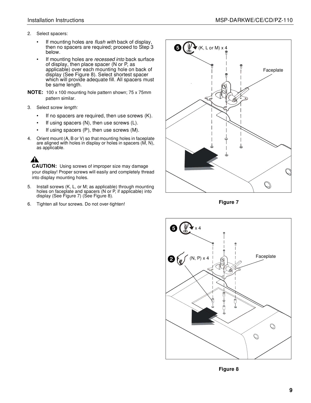
| then no spacers are required; proceed to Step 3 | 5 | (K, L or M) x 4 |
| below. |
|
|
| • If mounting holes are recessed into back surface |
|
|
| of display, then place spacer (N or P, as |
|
|
| applicable) over each mounting hole on back of |
| Faceplate |
| display (See Figure 8). Select shortest spacer |
|
|
| which will provide adequate fill. All spacers must |
|
|
| be same length. |
|
|
NOTE: 100 x 100 mounting hole pattern shown; 75 x 75mm |
|
| |
| pattern similar. |
|
|
3. | Select screw length: |
|
|
| • If no spacers are required, then use screws (K). |
|
|
| • If using spacers (N), then use screws (L). |
|
|
| • If using spacers (P), then use screws (M). |
|
|
4. | Orient mount (A, B or V) so that mounting holes in faceplate |
|
|
| are aligned with holes in display or holes in spacers (M, N), |
|
|
| as applicable. |
|
|
| CAUTION: Using screws of improper size may damage |
|
|
| your display! Proper screws will easily and completely thread |
|
|
| into display mounting holes. |
|
|
5. Install screws (K, L, or M; as applicable) through mounting |
|
| |
| holes on faceplate and spacers (N or P, if applicable) into |
|
|
| display (See Figure 7) (See Figure 8). |
|
|
6. Tighten all four screws. Do not | Figure 7 |
5 | x 4 |
|
2 | (N, P) x 4 | Faceplate |
|
Figure 8
9