Installation Instructions |
5.Partially thread a
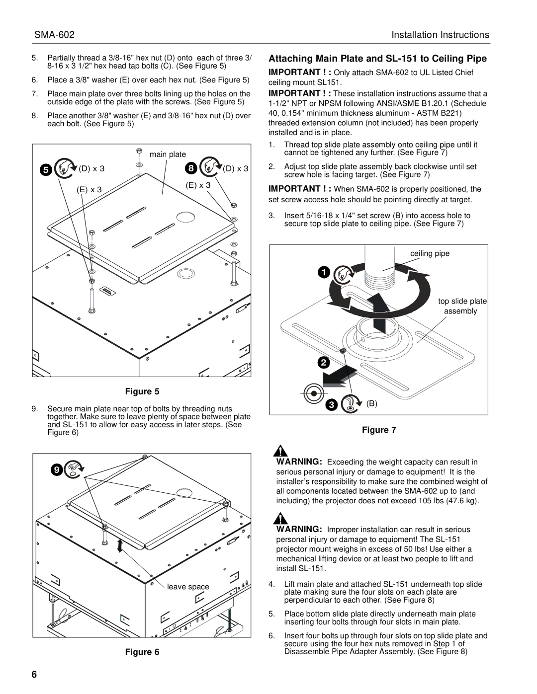
6.Place a 3/8" washer (E) over each hex nut. (See Figure 5)
7.Place main plate over three bolts lining up the holes on the outside edge of the plate with the screws. (See Figure 5)
8.Place another 3/8" washer (E) and
|
| main plate |
|
5 | (D) x 3 | 8 | (D) x 3 |
| (E) x 3 | (E) x 3 |
|
|
|
|
Figure 5
9.Secure main plate near top of bolts by threading nuts together. Make sure to leave plenty of space between plate and
Attaching Main Plate and SL-151 to Ceiling Pipe
IMPORTANT ! : Only attach
IMPORTANT ! : These installation instructions assume that a
1.Thread top slide plate assembly onto ceiling pipe until it cannot be tightened any further. (See Figure 7)
2.Adjust top slide plate assembly back clockwise until set screw hole is facing target. (See Figure 7)
IMPORTANT ! : When
3.Insert
| ceiling pipe |
1 |
|
| top slide plate |
| assembly |
2 |
|
3 | (B) |
Figure 7
9 |
leave space |
Figure 6
WARNING: Exceeding the weight capacity can result in serious personal injury or damage to equipment! It is the installer’s responsibility to make sure the combined weight of all components located between the
WARNING: Improper installation can result in serious personal injury or damage to equipment! The
4.Lift main plate and attached
5.Place bottom slide plate directly underneath main plate inserting four bolts through four slots in main plate.
6.Insert four bolts up through four slots on top slide plate and secure using the four hex nuts removed in Step 1 of Disassemble Pipe Adapter Assembly. (See Figure 8)
6