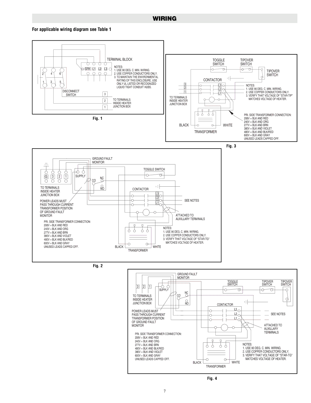
WIRING

For applicable wiring diagram see Table 1


TERMINAL BLOCK

GRN L1 L2

NOTES:

L3

TOGGLE TIPOVER

SWITCH SWITCH

2

4

6


1. USE 90 DEG. C. MIN. WIRING.


2. USE COPPER CONDUCTORS ONLY.


3. TO MAINTAIN THE ENVIRONMENTAL

1

3

5


RATING OF THIS ENCLOSURE, USE


ONLY UL LISTED OR RECOGNIZED


LIQUID TIGHT CONDUIT HUBS.


DISCONNECT

3


SWITCH


2

TO TERMINALS


INSIDE HEATER


1

JUNCTION BOX

Fig. 1


CONTACTOR

3

L3

2

L2

1

L1


TO TERMINALS

INSIDE HEATER

JUNCTION BOX

BLACK

WHITE

TRANSFORMER

TIPOVER

SWITCH

NOTES:

1.USE 90 DEG. C. MIN. WIRING.

2.USE COPPER CONDUCTORS ONLY.

3.VERIFY THAT VOLTAGE OF "STAR-TIP" MATCHES VOLTAGE OF HEATER.

PRI. SIDE TRANSFORMER CONNECTION: 208V = BLK AND RED

240V = BLK AND ORG

277V = BLK AND BRN

380V = BLK AND VIOLET

480V = BLK AND BLK/RED

600V = BLK AND GRAY UNUSED LEADS CAPPED OFF.

Fig. 3


GROUND FAULT


MONITOR


TOGGLE SWITCH

G

3

2

1

SUPPLY

NC


CO


TO TERMINALS


NO

CONTACTOR

INSIDE HEATER


L3

JUNCTION BOX


L2

POWER LEADS MUST


SEE NOTES

PASS THROUGH CURRENT


L1


TRANSFORMER POSITION


OF GROUND FAULT


ATTACHED TO

MONITOR


AUXILLARY TERMINALS

PRI. SIDE TRANSFORMER CONNECTION:


208V

= BLK AND RED


240V

= BLK AND ORG


NOTES:


1. USE 90 DEG. C. MIN. WIRING.

277V

= BLK AND BRN


380V

= BLK AND VIOLET


2. USE COPPER CONDUCTORS ONLY.


480V

= BLK AND BLK/RED


3. VERIFY THAT VOLTAGE OF "STAR-TG"


600V

= BLK AND GRAY


MATCHES VOLTAGE OF HEATER.

UNUSED LEADS CAPPED OFF.

BLACK


WHITE

TRANSFORMER

Fig. 2


GROUND FAULT


MONITOR

TOGGLE

TIPOVER


TIPOVER

3

2

1


SWITCH

SWITCH

SWITCH


SUPPLY

NC


TO TERMINALS

CO


INSIDE HEATER


JUNCTION BOX

NO

CONTACTOR


POWER LEADS MUST


L3


L2

SEE NOTES

PASS THROUGH CURRENT


TRANSFORMER POSITION


L1


OF GROUND FAULT


ATTACHED TO

MONITOR


AUXILLARY


PRI. SIDE TRANSFORMER CONNECTION:


TERMINALS


208V = BLK AND RED


240V = BLK AND ORG


NOTES:


277V = BLK AND BRN


480V = BLK AND BLK/RED


1. USE 90 DEG. C. MIN. WIRING.

380V = BLK AND VIOLET


2. USE COPPER CONDUCTORS ONLY.

600V = BLK AND GRAY


3. VERIFY THAT VOLTAGE OF "STAR-TG"

UNUSED LEADS CAPPED OFF.

BLACK

WHITE

MATCHES VOLTAGE OF HEATER.


TRANSFORMER


Fig. 4

7

Page 7
Image 7
Chromalox DS-50600 installation instructions Wiring

DS-50600 specifications

The Chromalox DS-50600 is a cutting-edge temperature control system designed for demanding applications across various industries. Known for its robust performance and advanced features, the DS-50600 stands out as an essential tool for maintaining precise thermal regulation in processes such as manufacturing, food processing, and chemical production.

At the heart of the Chromalox DS-50600 is its intuitive control technology. This advanced system boasts a high-resolution display that provides real-time temperature readings and system status, allowing operators to monitor processes continuously. The user-friendly interface enables easy navigation through menus, ensuring that even less experienced personnel can operate the system effectively.

One of the main features of the DS-50600 is its versatility in temperature control. It offers a wide temperature range capability, making it suitable for a multitude of applications. The system can be programmed to meet specific operational requirements, including precise heating and cooling cycles. This flexibility ensures optimal performance in diverse environments, accommodating varying substances and processes.

Another key characteristic of the Chromalox DS-50600 is its durability. Constructed with high-quality materials, the system is designed to withstand harsh operational conditions. Its robust design minimizes the risk of wear and failure, thereby extending the lifespan of the equipment and ensuring reliability.

Furthermore, the DS-50600 integrates advanced safety features, which are paramount in industrial applications. The system comes equipped with multiple safety alarms and shut-off capabilities, designed to protect both the equipment and personnel. Its smart technology can promptly detect any anomalies, allowing for immediate intervention before critical failures occur.

The energy efficiency of the Chromalox DS-50600 is another noteworthy attribute. Engineered to reduce energy consumption while maintaining optimal performance, this system helps organizations minimize their operational costs and environmental impact. By utilizing innovative heating technologies, the DS-50600 ensures effective energy use without compromising on performance.

In conclusion, the Chromalox DS-50600 is an exemplary thermal control system that blends advanced technology, versatility, and durability. With its user-friendly interface, broad temperature range, and robust safety features, the DS-50600 is tailored for professionals seeking reliable and efficient temperature management solutions in any demanding industrial environment.