INSTALLATION
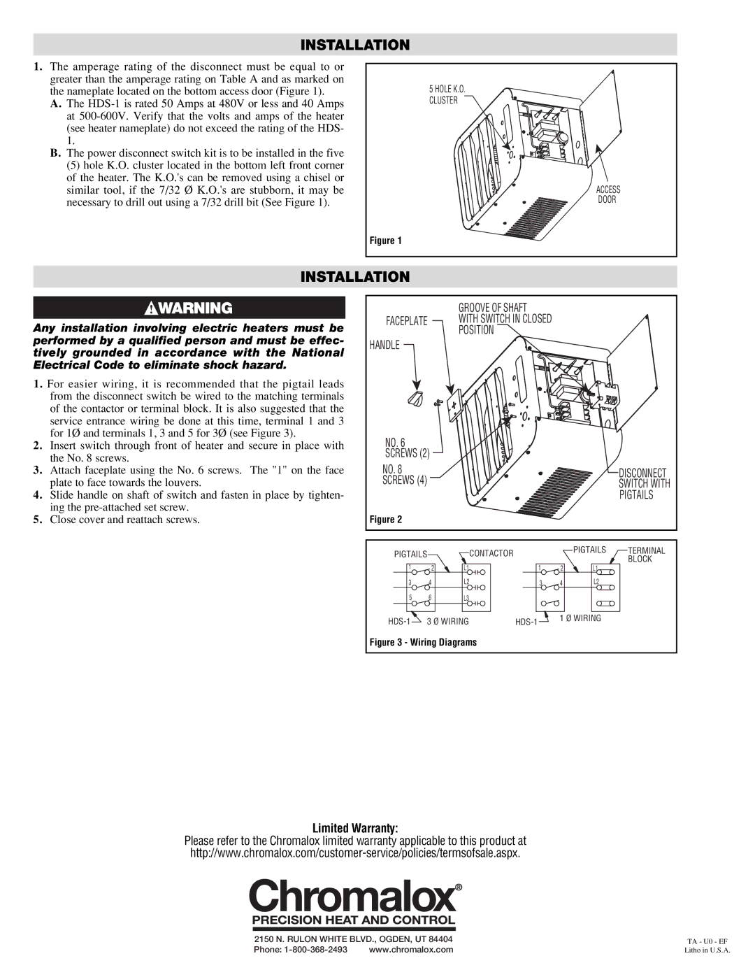
1.The amperage rating of the disconnect must be equal to or greater than the amperage rating on Table A and as marked on the nameplate located on the bottom access door (Figure 1).
A.The
B.The power disconnect switch kit is to be installed in the five
(5) hole K.O. cluster located in the bottom left front corner of the heater. The K.O.'s can be removed using a chisel or similar tool, if the 7/32 Ø K.O.'s are stubborn, it may be necessary to drill out using a 7/32 drill bit (See Figure 1).
5 HOLE K.O. |
CLUSTER |
ACCESS |
DOOR |
Figure 1 |
INSTALLATION
Any installation involving electric heaters must be performed by a qualified person and must be effec- tively grounded in accordance with the National Electrical Code to eliminate shock hazard.
1.For easier wiring, it is recommended that the pigtail leads from the disconnect switch be wired to the matching terminals of the contactor or terminal block. It is also suggested that the service entrance wiring be done at this time, terminal 1 and 3 for 1Ø and terminals 1, 3 and 5 for 3Ø (see Figure 3).
2.Insert switch through front of heater and secure in place with the No. 8 screws.
3.Attach faceplate using the No. 6 screws. The "1" on the face plate to face towards the louvers.
4.Slide handle on shaft of switch and fasten in place by tighten- ing the
5.Close cover and reattach screws.
|
| GROOVE OF SHAFT |
|
|
|
| |
FACEPLATE |
| WITH SWITCH IN CLOSED |
|
|
| ||
|
| POSITION |
|
|
|
| |
HANDLE |
|
|
|
|
|
| |
NO. 6 |
|
|
|
|
|
| |
SCREWS (2) |
|
|
|
|
| ||
NO. 8 |
|
|
|
|
| DISCONNECT | |
SCREWS (4) |
|
|
|
|
| SWITCH WITH | |
|
|
|
|
|
| PIGTAILS | |
Figure 2 |
|
|
|
|
|
| |
PIGTAILS |
| CONTACTOR |
|
| PIGTAILS | TERMINAL | |
|
|
|
| BLOCK | |||
1 | 2 | L1 | 1 | 2 | L1 | ||
| |||||||
3 | 4 | L2 | 3 | 4 | L2 |
| |
5 | 6 | L3 |
|
|
|
| |
3 Ø WIRING | 1 Ø WIRING | ||
|
Figure 3 - Wiring Diagrams
Limited Warranty:
Please refer to the Chromalox limited warranty applicable to this product at
2150 N. RULON WHITE BLVD., OGDEN, UT 84404 | TA - U0 - EF | |
Phone: | www.chromalox.com | Litho in U.S.A. |