Installation, Operation
and
RENEWAL PARTS IDENTIFICATION
Please familiarize yourself with these instructions before attempting to install or connect this radiant heater
|
|
|
|
|
|
|
|
|
|
|
|
|
|
|
|
|
|
|
|
|
|
|
|
|
|
|
|
|
|
|
|
|
|
|
|
|
|
| 4 |
|
|
| |
|
|
|
| |||||||
|
|
|
| |||||||
|
|
|
|
|
| (Supersedes |
| |||
JULY, 2006
Type U-RP Radiant Heater
|
|
|
|
|
|
|
|
| Specifications – Table A |
|
|
|
|
| |
|
|
|
|
|
|
|
|
|
|
|
|
|
|
|
|
|
|
|
|
|
|
|
|
|
|
|
|
| Dimensions (In.) |
| |
|
|
|
|
|
|
|
|
|
|
| B | C | D | ||
|
|
|
|
|
|
|
|
|
|
| Overall | Heated | Overall | ||
|
|
|
|
|
|
|
|
| Model | Volts | kW | A | Length | Length | Height |
|
|
|
|
|
|
|
|
| 208 or 275 | 13.2 | 48 | 12 | |||
|
|
|
|
|
| A |
| ||||||||
|
|
|
|
|
|
| 240 or 480 | 13.2 | 48 | 12 | |||||
|
|
|
|
|
|
|
|
|
|
|
|
|
|
|
|
|
|
|
|
|
|
|
|
| 208 or 275 | 26.4 | 48 | 24 | |||
|
|
|
|
|
|
|
|
| 240 or 480 | 26.4 | 48 | 24 | |||
|
|
|
| ||||||||||||
|
|
|
| 208 or 275 | 18 | 66 | 12 | ||||||||
|
|
|
|
|
|
|
|
| |||||||
|
|
|
|
|
|
|
|
| 240 or 480 | 18 | 66 | 12 | |||
D |
|
|
|
|
|
|
| 208 or 275 | 36 | 66 | 24 | ||||
|
|
|
|
|
|
|
|
| 240 or 480 | 36 | 66 | 24 | |||
C
B
Before installing
1.Open carton and remove heater at the place of installation.
2.Check nameplate volt and watt rating against your power supply voltage and heating requirements of your installation. This name- plate is located on one end of the heater.
MOUNTING
1.Framing: Fabricate structural support using angle iron or contin- uous slot metal framing (manufactured by others). Dimension framing per Table B and Figure 1 for your size panel.
| Mtg. Bracket (Typ.) |
| |
Opening |
| ||
|
| ||
A |
| I | D |
|
| ||
| G | H |
|
F |
|
| |
|
|
| |
Terminal Box Cover |
|
| |
| Figure 1 – Aluminum Extruded Section |
| |
Mounting – Table A
| No. of Mounting |
| Dimensions (In.) |
| ||
|
|
|
|
| ||
Model | Brackets | F | G | H | I | |
2 | — | — | ||||
|
|
|
|
| ||
2 | — | — | ||||
|
|
|
|
| ||
3 | ||||||
|
|
|
|
| ||
3 | ||||||
|
|
|
|
| ||
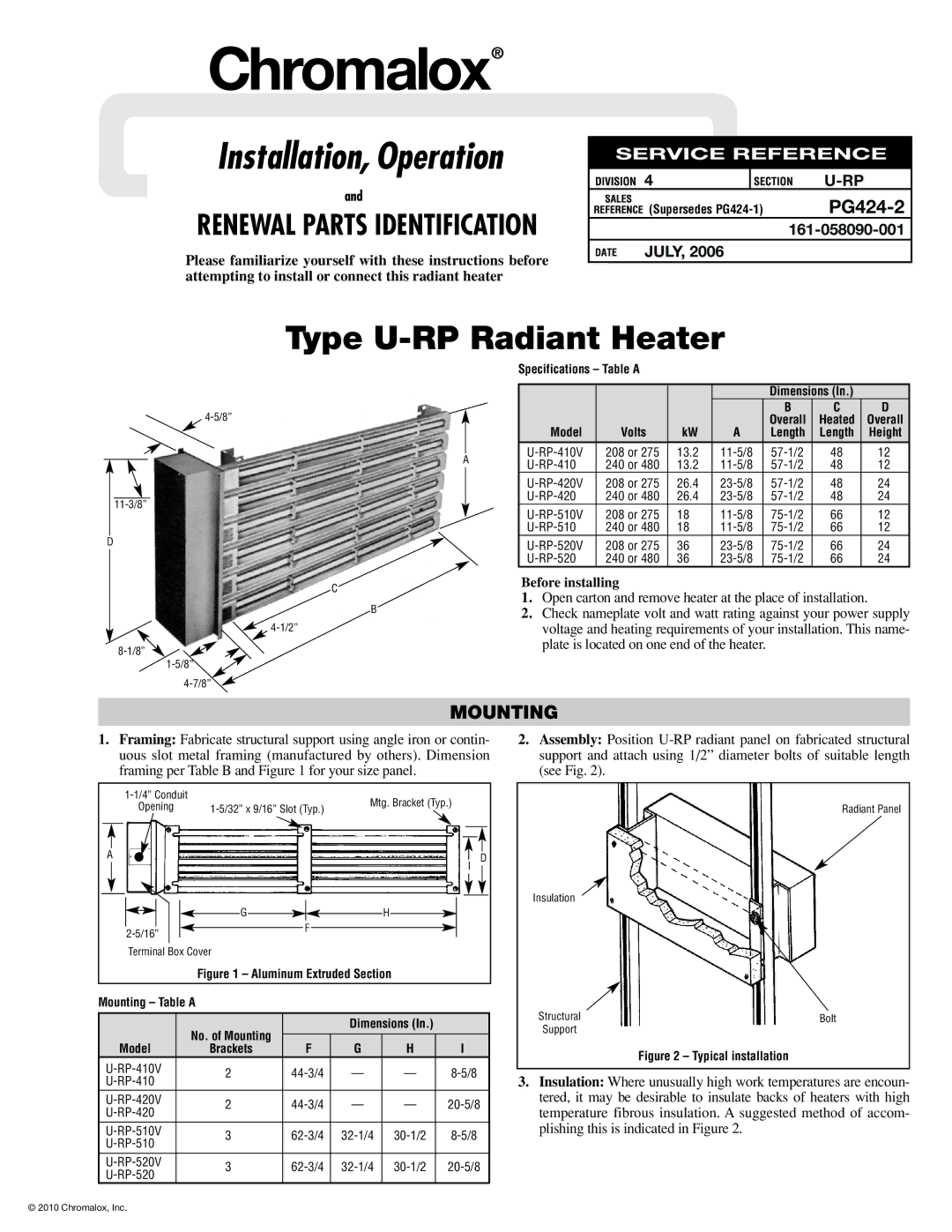
2.Assembly: Position
Radiant Panel
Insulation
Structural | Bolt |
Support |
|
Figure 2 – Typical installation
3.Insulation: Where unusually high work temperatures are encoun- tered, it may be desirable to insulate backs of heaters with high temperature fibrous insulation. A suggested method of accom- plishing this is indicated in Figure 2.
© 2010 Chromalox, Inc.