OPERATION
RECOMMENDED START-UP PROCEDURES
1.Close globe valve on outlet side of boiler. (Customer Supplied)
2.Turn on boiler and allow pressure to build up to operating pressure.
3.Only open globe valve by quarter turns at first, introducing small- er amounts of steam into process. Avoid opening globe valve all at once. This will eliminate the possibility of evacuating the boiler of water caused by the suddenly increased boiling of the water in the vessel as the pressure is reduced. On boilers where constant pres- sure is not maintained, globe valve should be kept partially closed. This will maintain a constant head on the boiler and stabilize any fluctuation in boiler water level.
NOTE: For best boiler performance, a steam valve 1/4” smaller than size of safety valve should be plumbed as close as practicable to steam outlet.
MANUAL BLOWDOWN INSTRUCTIONS
Blowdown is an essential part of boiler operation. It is the best pre- ventive maintenance you can give your boiler and will add years of life to the unit. Make sure a blowdown schedule is established and fol- lowed regularly.
In extremely hard water areas blowdown is necessary once a day. In soft water areas, once each week. If there is a particular problem which applies to your own local water condition other than mineral content, take this into consideration in determining which schedule is to be followed.
1.At the end of the working day, while boiler is still operating, turn switch to the OFF position and close water supply valve.
2.If
3.It is preferable to connect the blowdown valve directly into a drainage system. If this is done, the boiler can be discharged at operating pressure.
4.When discharge is complete and boiler is drained –
a.close the blowdown valve;
b.open water supply valve;
c.put boiler switch to the “ON” position; and, (d) close wall mounted safety switch.
5.When refilling is complete turn off the boiler switch unless further operation is desirable.
6.If you have been supplied with a Manual Reset Low Water control as required in some states, the reset button on the control must be pushed before boiler will begin developing pressure. (Do not push reset until boiler has filled with water.) The use of chemical boiler cleaning compounds in these boilers voids all warranties unless approved by manufacturer. Some compounds will damage copper- sheathed heating elements, thereby shortening their life.
AUTOMATIC BLOWDOWN INSTRUCTIONS (IF FURNISHED) (See Figures 14 and 15)
The Automatic Blowdown is a device which automatically starts up your boiler in the morning; shuts it down at night and blows down (partially drains) the main boiler drain and the low water
The heart of the unit is an electrically operated straight through type ball valve. It is specially designed to handle dirty, corrosive fluids and particles without requiring cleaning or the use of a strainer.
Both the valve and the boiler are controlled by an electric control unit which indicates with pilot lights when the drain valve is in the opened or closed position and when the boiler is ON or OFF. In addition to the automatic control function, the unit has a push button which momen- tarily
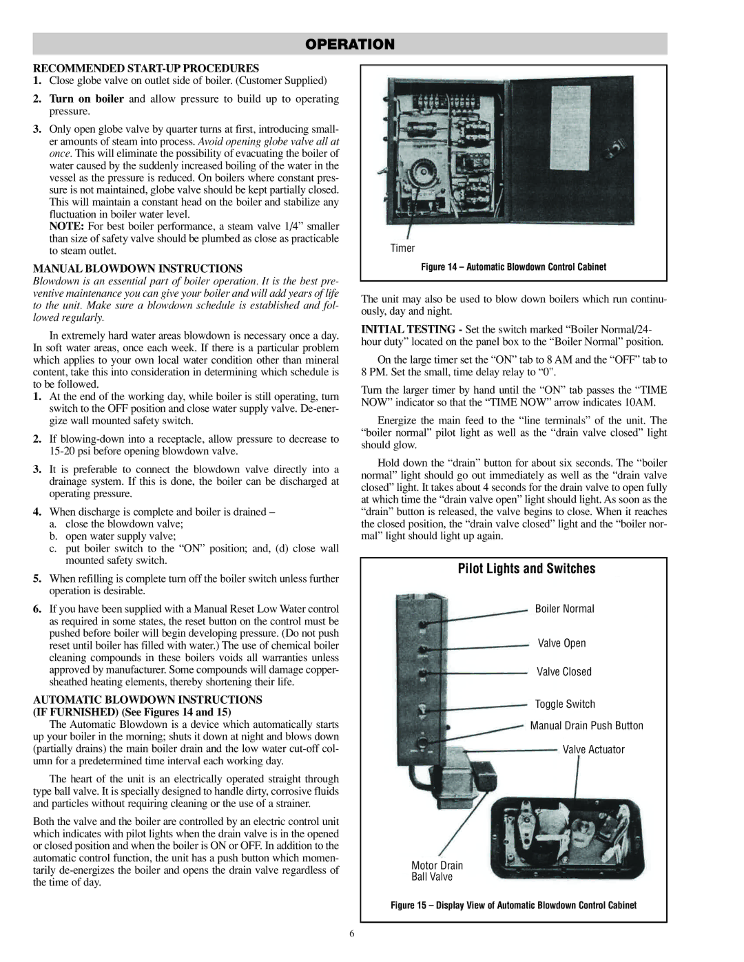
Timer
Figure 14 – Automatic Blowdown Control Cabinet
The unit may also be used to blow down boilers which run continu- ously, day and night.
INITIAL TESTING - Set the switch marked “Boiler Normal/24- hour duty” located on the panel box to the “Boiler Normal” position.
On the large timer set the “ON” tab to 8 AM and the “OFF” tab to 8 PM. Set the small, time delay relay to “0".
Turn the larger timer by hand until the “ON” tab passes the “TIME NOW” indicator so that the “TIME NOW” arrow indicates 10AM.
Energize the main feed to the “line terminals” of the unit. The “boiler normal” pilot light as well as the “drain valve closed” light should glow.
Hold down the “drain” button for about six seconds. The “boiler normal” light should go out immediately as well as the “drain valve closed” light. It takes about 4 seconds for the drain valve to open fully at which time the “drain valve open” light should light. As soon as the “drain” button is released, the valve begins to close. When it reaches the closed position, the “drain valve closed” light and the “boiler nor- mal” light should light up again.
Pilot Lights and Switches
Boiler Normal
Valve Open
Valve Closed
Toggle Switch
Manual Drain Push Button
Valve Actuator
Motor Drain
Ball Valve
Figure 15 – Display View of Automatic Blowdown Control Cabinet
6