Chromalox PQ410-4 service manual Piping General, Expansion Tank Location, Piping Restrictions

Models: PQ410-4

1 6
Download 6 pages 44.38 Kb
Page 2
Image 2
PIPING GENERAL

3.

PIPING RESTRICTIONS


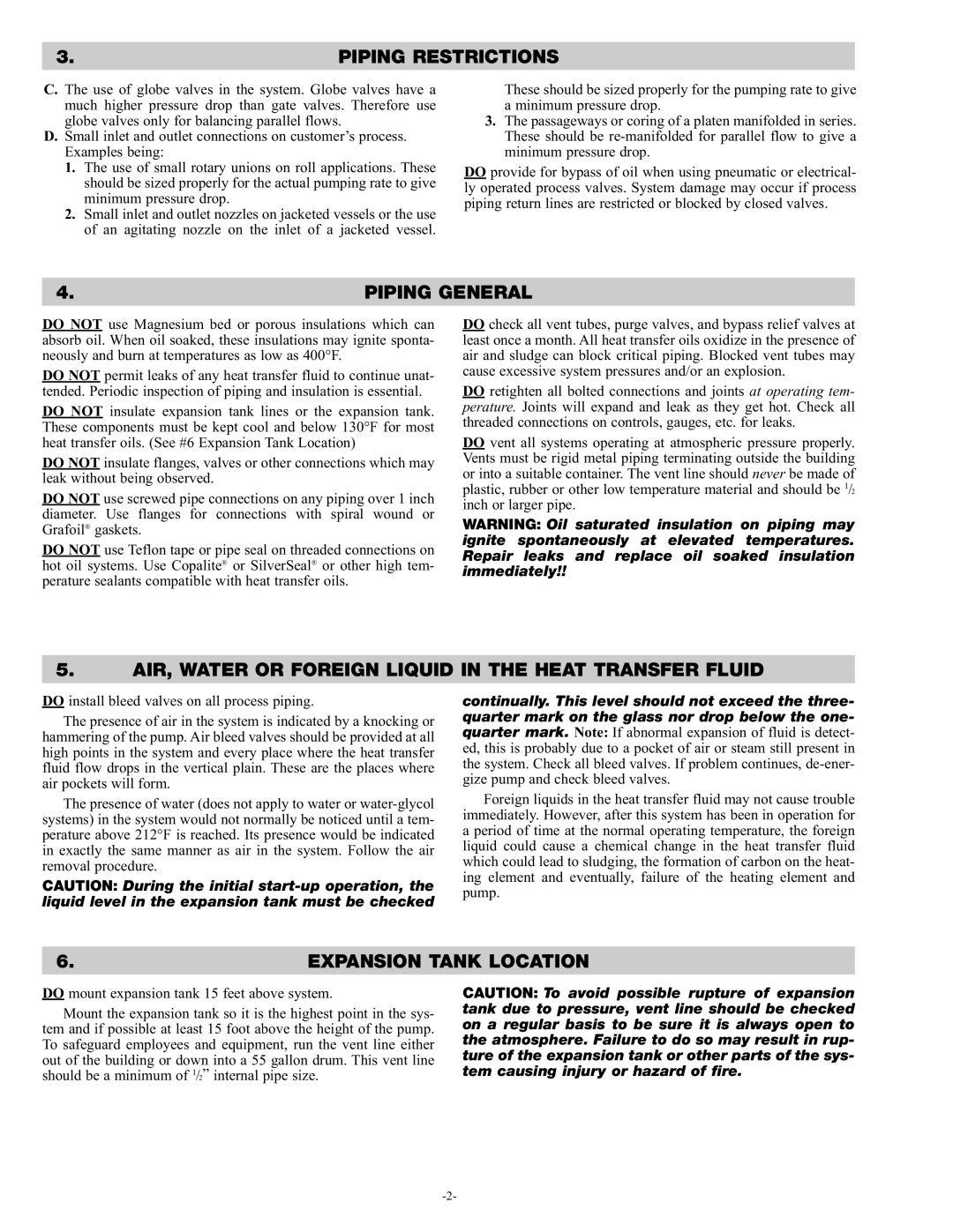
C. The use of globe valves in the system. Globe valves have a much higher pressure drop than gate valves. Therefore use globe valves only for balancing parallel flows.

D.Small inlet and outlet connections on customer’s process. Examples being:

1.The use of small rotary unions on roll applications. These should be sized properly for the actual pumping rate to give minimum pressure drop.

2.Small inlet and outlet nozzles on jacketed vessels or the use of an agitating nozzle on the inlet of a jacketed vessel.

These should be sized properly for the pumping rate to give a minimum pressure drop.

3.The passageways or coring of a platen manifolded in series. These should be re-manifolded for parallel flow to give a minimum pressure drop.

DO provide for bypass of oil when using pneumatic or electrical- ly operated process valves. System damage may occur if process piping return lines are restricted or blocked by closed valves.

4.

PIPING GENERAL


DO NOT use Magnesium bed or porous insulations which can absorb oil. When oil soaked, these insulations may ignite sponta- neously and burn at temperatures as low as 400°F.

DO NOT permit leaks of any heat transfer fluid to continue unat- tended. Periodic inspection of piping and insulation is essential.

DO NOT insulate expansion tank lines or the expansion tank. These components must be kept cool and below 130°F for most heat transfer oils. (See #6 Expansion Tank Location)

DO NOT insulate flanges, valves or other connections which may leak without being observed.

DO NOT use screwed pipe connections on any piping over 1 inch diameter. Use flanges for connections with spiral wound or Grafoil® gaskets.

DO NOT use Teflon tape or pipe seal on threaded connections on hot oil systems. Use Copalite® or SilverSeal® or other high tem- perature sealants compatible with heat transfer oils.

DO check all vent tubes, purge valves, and bypass relief valves at least once a month. All heat transfer oils oxidize in the presence of air and sludge can block critical piping. Blocked vent tubes may cause excessive system pressures and/or an explosion.

DO retighten all bolted connections and joints at operating tem- perature. Joints will expand and leak as they get hot. Check all threaded connections on controls, gauges, etc. for leaks.

DO vent all systems operating at atmospheric pressure properly. Vents must be rigid metal piping terminating outside the building or into a suitable container. The vent line should never be made of plastic, rubber or other low temperature material and should be 1/2 inch or larger pipe.

WARNING: Oil saturated insulation on piping may ignite spontaneously at elevated temperatures. Repair leaks and replace oil soaked insulation immediately!!

5.AIR, WATER OR FOREIGN LIQUID IN THE HEAT TRANSFER FLUID

DO install bleed valves on all process piping.

The presence of air in the system is indicated by a knocking or hammering of the pump. Air bleed valves should be provided at all high points in the system and every place where the heat transfer fluid flow drops in the vertical plain. These are the places where air pockets will form.

The presence of water (does not apply to water or water-glycol systems) in the system would not normally be noticed until a tem- perature above 212°F is reached. Its presence would be indicated in exactly the same manner as air in the system. Follow the air removal procedure.

CAUTION: During the initial start-up operation, the liquid level in the expansion tank must be checked

continually. This level should not exceed the three- quarter mark on the glass nor drop below the one- quarter mark. Note: If abnormal expansion of fluid is detect- ed, this is probably due to a pocket of air or steam still present in the system. Check all bleed valves. If problem continues, de-ener- gize pump and check bleed valves.

Foreign liquids in the heat transfer fluid may not cause trouble immediately. However, after this system has been in operation for a period of time at the normal operating temperature, the foreign liquid could cause a chemical change in the heat transfer fluid which could lead to sludging, the formation of carbon on the heat- ing element and eventually, failure of the heating element and pump.

6.

EXPANSION TANK LOCATION


DO mount expansion tank 15 feet above system.

Mount the expansion tank so it is the highest point in the sys- tem and if possible at least 15 foot above the height of the pump. To safeguard employees and equipment, run the vent line either out of the building or down into a 55 gallon drum. This vent line should be a minimum of 1/2” internal pipe size.

CAUTION: To avoid possible rupture of expansion tank due to pressure, vent line should be checked on a regular basis to be sure it is always open to the atmosphere. Failure to do so may result in rup- ture of the expansion tank or other parts of the sys- tem causing injury or hazard of fire.

-2-

Page 2
Image 2
Chromalox PQ410-4 service manual Piping General, Expansion Tank Location, Piping Restrictions