Manuals
/
Regency
/
Household Appliance
/
Indoor Fireplace
Regency
P33-LP3, P33-NG3
installation manual
Parts List
Models:
P33-NG3
P33-LP3
1
42
48
48
Download
48 pages
9.74 Kb
39
40
41
42
43
44
45
46
Install
Parts list
Wiring Diagram
Thermostat Wire Table
Warranty
Dimension
Maintenance
Top Standoff Assembly
Lighting Procedure
Pilot Adjustment
Page 42
Image 42
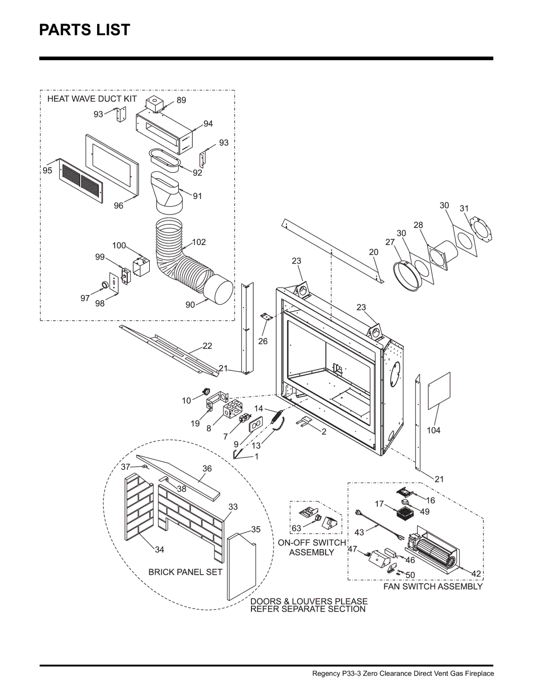
PARTS LIST
Regency
P33-3
Zero Clearance Direct Vent Gas Fireplace
Page 41
Page 43
Page 42
Image 42
Page 41
Page 43
Contents
P33-3 Zero Clearance
Information for MOBILE/MANUFACTURED Homes After First Sale
To the New Owner
Table of Contents
Safety Label
Save These Instructions
Installation
General Safety Information
Before YOU Start
Locating Your GAS Stove
Installation Checklist
Unit Dimensions
Duct System Option
Clearances are not adhered to
Clearancescombustible Mantels
Mantel LEG Clearances
Fire hazard is an extreme risk if these
Simpson Dura-Vent Minimum Clearances
Framing and Finishing
Rear Termination
Vertical Termination or Vertical Rise with Horizontal
Venting Introduction
Unit Assembly Prior to Installation
Top Standoff Assembly
Top Facing Support Side Nailing Strips
Vent
Vent terminal Air supply outlet
Regency Direct Vent System Flex Horizontal Terminations only
Installation Procedures
For Regency Direct Vent System Flex
Max. Wall Vent Length
Flat Wall Installation
Rigid Pipe Venting Systems
Thickness inches Required inches
Rigid Pipe Venting Components List
Description Simpson Dura-Vent Selkirk
Direct VentGS R Direct-Temp TM
Rigid Pipe Venting Arrangements Vertical Terminations
Propane & Natural Gas
Installation
Rigid Pipe Venting Arrangements Horizontal Terminations
Regency Direct Vent System Flex
Horizontal Venting with Two 2 90o Elbows
Horizontal Venting with Three 3 90o Elbows
Option + H1
Option
Vertical Venting with Two 2 90o Elbows
Option + V1 H + H1
+ V1 With these options, max. total
Vertical Venting with Three 3 90o Elbows
Description
Vertical Termination With CO-LINEAR Flex System
Required Parts
Alternate Approved Caps
Installation
Horizontal Installations
Below Grade Snorkel Installation
Snorkel Terminations
GAS Line Installation
Vertical Termination
High Elevation
Pilot Adjustment
GAS Pipe Pressure Testing
T. Valve Description
Conversion Kit Contains
Notch
LOG SET Installation
Optional Brick Panels
BracketBracket
Cutout
Standard Flush Door
Optional Flush Trim
5th Grate Tab
Optional BAY Door
Flush Louvers
Double Screen Door
Bay louvers Must be used With the Bay glass option
Bay Louver Top Heat Shield
BAY Louvers
Flush Louver Top Heat Shield
Burner ON/OFF Control box
Full Screen Front
Cut-Out Oblong Hole Top Flange Bottom
Cut-Outs
Hinge Location Bottom Grill
Top Grill
Optional Wall Switch
Thermostat Wire Table
Wiring Diagram
Do not cut the ground terminal off under any circumstances
Diagram Secure left side with 2 screws
Installing the Optional FAN
Shut the power off
Secure the 2 boxes together With one screw
Operating Instructions
Copy of the Lighting Plate Instructions
Aeration Adjustment
Lighting Procedure
Shutdown Procedure
Operating Instructions
LOG Replacement
Maintenance
Maintenance Instructions
Normal Operating Sounds GAS Appliances
Glass Gasket
Flush Glass Replacement
Thermopile Thermocouple
Door Glass
Removing Valve
Installing Valve
Diagram 3 Lift out Valve Tray Assembly
Shut off the gas supply
Parts List
Description
Parts List
Burner & Log Assembly
Part Description
Flush Front & Louvers
Bay Front & Louvers
Regency P33-3 Zero Clearance Direct Vent Gas Fireplace
Warranty
Conditions
Installer Please complete the following information
Top
Page
Image
Contents