INSTALLATION
UNIT ASSEMBLY
PRIOR TO INSTALLATION
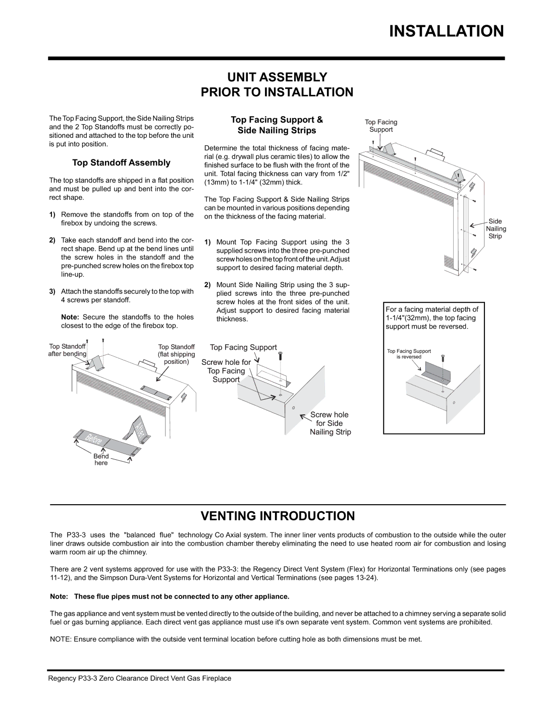
The Top Facing Support, the Side Nailing Strips and the 2 Top Standoffs must be correctly po- sitioned and attached to the top before the unit is put into position.
Top Standoff Assembly
The top standoffs are shipped in a fl at position and must be pulled up and bent into the cor- rect shape.
1)Remove the standoffs from on top of the fi rebox by undoing the screws.
2)Take each standoff and bend into the cor- rect shape. Bend up at the bend lines until the screw holes in the standoff and the
3)Attach the standoffs securely to the top with 4 screws per standoff.
Note: Secure the standoffs to the holes closest to the edge of the fi rebox top.
Top Facing Support &
Side Nailing Strips
Determine the total thickness of facing mate- rial (e.g. drywall plus ceramic tiles) to allow the
finished surface to be fl ush with the front of the unit. Total facing thickness can vary from 1/2" (13mm) to
The Top Facing Support & Side Nailing Strips can be mounted in various positions depending on the thickness of the facing material.
1)Mount Top Facing Support using the 3 supplied screws into the three
2)Mount Side Nailing Strip using the 3 sup- plied screws into the three
For a facing material depth of
VENTING INTRODUCTION
The
There are 2 vent systems approved for use with the
Note: These flue pipes must not be connected to any other appliance.
The gas appliance and vent system must be vented directly to the outside of the building, and never be attached to a chimney serving a separate solid fuel or gas burning appliance. Each direct vent gas appliance must use it's own separate vent system. Common vent systems are prohibited.
NOTE: Ensure compliance with the outside vent terminal location before cutting hole as both dimensions must be met.
Regency