INSTALLATION
WIRING DIAGRAM
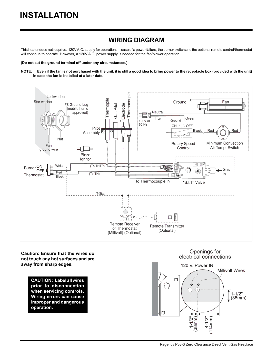
This heater does not require a 120V A.C. supply for operation. In case of a power failure, the burner switch and the optional remote control/thermostat will continue to operate. However, a 120V A.C. power supply is needed for the fan/blower operation.
(Do not cut the ground terminal off under any circumstances.)
NOTE: Even if the fan is not purchased with the unit, it is still a good idea to bring power to the receptacle box (provided with the unit) in case the fan is installed at a later date.
|
| Lockwasher | Thermopile |
|
| Thermocouple |
|
|
|
|
|
|
|
|
| |
Star washer | #8 Ground Lug | GasPilot | Electrode |
|
| Ground |
|
|
|
| Fan | |||||
|
|
|
|
|
|
|
|
|
|
|
| |||||
|
|
| (mobile home |
|
|
|
|
|
|
|
|
| ||||
|
|
| approved) |
| Neutral |
|
|
|
|
|
| |||||
|
|
|
|
| Live |
| Green |
|
|
|
|
| ||||
|
|
|
|
|
|
| 120V AC |
| Ground |
|
|
|
|
| ||
|
|
|
|
|
|
| 60 Hz |
|
| ON | OFF |
|
|
|
|
|
|
|
| Pilot |
|
|
|
|
|
|
|
|
|
|
| ||
|
|
|
|
|
|
|
|
|
| Black | Red | Red | ||||
|
|
| Assembly |
|
|
|
|
|
|
| ||||||
|
|
|
|
|
|
|
|
|
|
|
|
|
|
|
| |
|
| Nut |
|
|
|
|
|
|
|
|
|
|
|
|
|
|
|
| Fan |
|
|
|
|
|
|
| Rotary Speed |
|
|
| Minimum Convection | ||
|
|
|
|
|
|
|
|
|
| Control |
|
|
| Air Temp. Switch | ||
| ground wire |
|
|
|
|
|
|
|
|
|
|
| ||||
|
|
|
|
|
|
|
|
|
|
|
|
|
|
| ||
|
|
| Piezo |
|
|
|
|
|
|
|
|
|
|
|
|
|
|
|
| Ignitor |
|
|
|
|
|
|
|
|
|
|
|
|
|
Burner | ON | White | (To THTP) |
|
|
|
|
|
| Brown | O |
|
|
|
| Gas |
|
|
|
|
|
|
|
|
| White |
|
|
|
| |||
OFF |
|
|
|
|
|
|
|
| L | OFF |
|
|
| |||
|
|
|
|
|
|
|
|
|
|
|
| P |
| |||
| Red | (To TH) |
|
|
|
|
|
|
| I H | NO T | O | L |
| In | |
Thermostat |
|
|
|
|
|
|
|
|
|
|
| |||||
Black |
|
|
|
|
|
|
|
|
|
|
|
| ||||
|
|
|
|
|
|
|
|
|
|
|
|
|
| |||
|
|
|
|
|
|
|
|
|
|
|
|
|
|
|
| |
|
|
|
|
|
|
| To Thermocouple IN | "S.I.T" Valve |
|
| ||||||
|
|
|
|
|
|
|
|
|
|
|
|
| ||||
|
|
|
|
|
|
|
|
|
|
|
|
|
|
|
| |
|
|
|
|
|
| ON | OFF |
|
| Regency |
|
|
|
|
|
|
|
|
|
|
|
|
|
|
|
|
|
|
|
|
|
| |
|
|
|
|
| Remote Receiver | Remote Transmitter |
|
|
|
|
| |||||
|
|
|
|
| or Thermostat |
|
|
|
|
| ||||||
|
|
|
|
|
| (Optional) |
|
|
|
|
|
| ||||
|
|
|
| (Millivolt) (Optional) |
|
|
|
|
|
|
| |||||
|
|
|
|
|
|
|
|
|
|
|
|
| ||||
Caution: Ensure that the wires do not touch any hot surfaces and are away from sharp edges.
CAUTION: Label all wires prior to disconnection when servicing controls. Wiring errors can cause improper and dangerous operation.
Regency