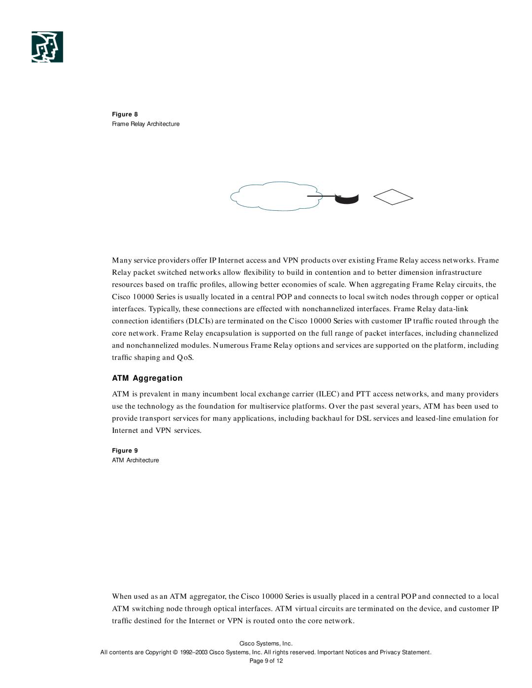
Figure 8
Frame Relay Architecture
|
| Clear Channel |
|
Business |
| Interface |
|
T1/E1 | Cisco |
| |
Customer |
| ||
| 10000 |
| |
|
| IP Network | |
|
| Series | |
|
|
| |
| Frame Relay |
|
|
| IP |
| IP |
| Frame Relay/DLC1 |
|
|
| SONET/SDH |
|
|
Many service providers offer IP Internet access and VPN products over existing Frame Relay access networks. Frame Relay packet switched networks allow flexibility to build in contention and to better dimension infrastructure resources based on traffic profiles, allowing better economies of scale. When aggregating Frame Relay circuits, the Cisco 10000 Series is usually located in a central POP and connects to local switch nodes through copper or optical interfaces. Typically, these connections are effected with nonchannelized interfaces. Frame Relay
ATM Aggregation
ATM is prevalent in many incumbent local exchange carrier (ILEC) and PTT access networks, and many providers use the technology as the foundation for multiservice platforms. Over the past several years, ATM has been used to provide transport services for many applications, including backhaul for DSL services and
Figure 9
ATM Architecture
|
| ATM |
|
Business |
| Interface |
|
T1/E1 | Cisco |
| |
Customer |
| ||
| 10000 |
| |
|
| IP Network | |
|
| Series | |
|
|
| |
| ATM |
|
|
| IP |
| IP |
| RFC 1483 |
|
|
| SONET/SDH |
|
|
When used as an ATM aggregator, the Cisco 10000 Series is usually placed in a central POP and connected to a local ATM switching node through optical interfaces. ATM virtual circuits are terminated on the device, and customer IP traffic destined for the Internet or VPN is routed onto the core network.
Cisco Systems, Inc.
All contents are Copyright ©
Page 9 of 12