Distance and Pinout Information
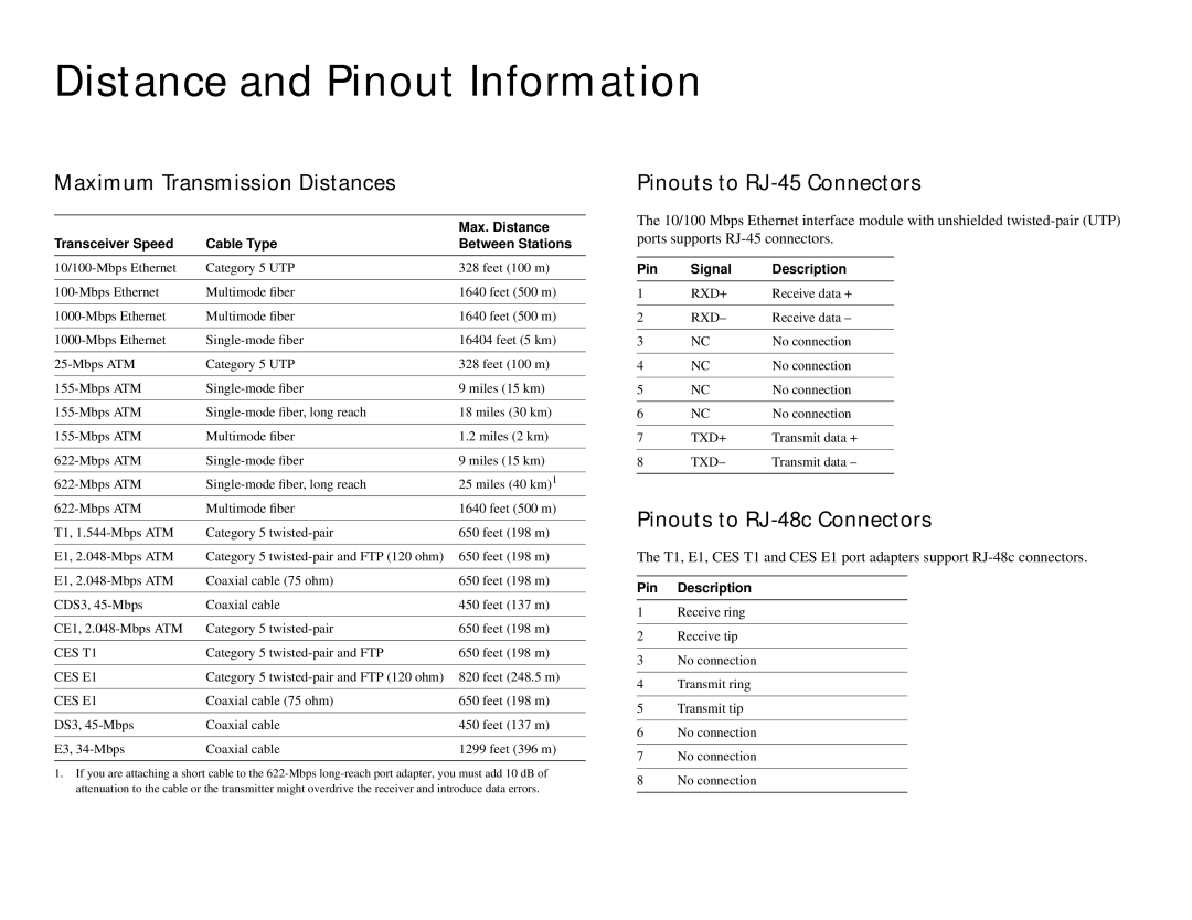
Maximum Transmission Distances
|
| Max. Distance |
Transceiver Speed | Cable Type | Between Stations |
|
|
|
Category 5 UTP | 328 feet (100 m) | |
|
|
|
Multimode fiber | 1640 feet (500 m) | |
|
|
|
Multimode fiber | 1640 feet (500 m) | |
|
|
|
16404 feet (5 km) | ||
|
|
|
Category 5 UTP | 328 feet (100 m) | |
|
|
|
9 miles (15 km) | ||
|
|
|
18 miles (30 km) | ||
|
|
|
Multimode fiber | 1.2 miles (2 km) | |
|
|
|
9 miles (15 km) | ||
|
|
|
25 miles (40 km) 1 | ||
Multimode fiber | 1640 feet (500 m) | |
|
|
|
T1, | Category 5 | 650 feet (198 m) |
|
|
|
E1, | Category 5 | 650 feet (198 m) |
|
|
|
E1, | Coaxial cable (75 ohm) | 650 feet (198 m) |
|
|
|
CDS3, | Coaxial cable | 450 feet (137 m) |
|
|
|
CE1, | Category 5 | 650 feet (198 m) |
|
|
|
CES T1 | Category 5 | 650 feet (198 m) |
|
|
|
CES E1 | Category 5 | 820 feet (248.5 m) |
|
|
|
CES E1 | Coaxial cable (75 ohm) | 650 feet (198 m) |
|
|
|
DS3, | Coaxial cable | 450 feet (137 m) |
|
|
|
E3, | Coaxial cable | 1299 feet (396 m) |
|
|
|
1.If you are attaching a short cable to the
Pinouts to RJ-45 Connectors
The 10/100 Mbps Ethernet interface module with unshielded
Pin | Signal | Description |
1 | RXD+ | Receive data + |
|
|
|
2 | RXD– | Receive data – |
|
|
|
3 | NC | No connection |
|
|
|
4 | NC | No connection |
|
|
|
5 | NC | No connection |
|
|
|
6 | NC | No connection |
|
|
|
7 | TXD+ | Transmit data + |
|
|
|
8 | TXD– | Transmit data – |
|
|
|
Pinouts to RJ-48c Connectors
The T1, E1, CES T1 and CES E1 port adapters support
Pin Description
1Receive ring
2Receive tip
3No connection
4Transmit ring
5Transmit tip
6No connection
7No connection
8No connection