Grounding the Chassis
Warning
Warning
Warning
This equipment must be grounded. Never defeat the ground conductor or operate the equipment in the absence of a suitably installed ground conductor. Contact the appropriate electrical inspection authority or an electrician if you are uncertain that suitable grounding is available. Statement 1024
During this procedure, wear grounding wrist straps to avoid ESD damage to the card. Do not directly touch the backplane with your hand or any metal tool, or you could shock yourself. Statement 94
This equipment needs to be grounded. Use a green and yellow 14 AWG ground wire to connect the host to earth ground during normal use. Statement 190
To connect the chassis to a reliable earth ground, using a ring terminal and size 14 AWG (2 mm2) wire, follow these steps:
Step 1 Strip one end of the ground wire to expose approximately 3/4 inch (20 mm) of conductor.
Step 2 Crimp the 14 AWG green ground wire to a UL Listed/CSA certified ring terminal, using a crimping tool that is recommended by the ring terminal manufacturer. The ring terminal provided on the back panel of the router is suitable for a No. 6 grounding screw.
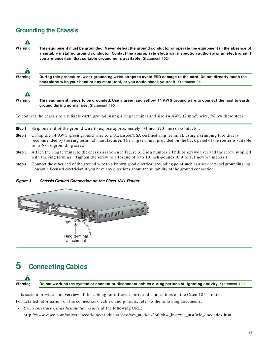
Step 3 Attach the ring terminal to the chassis as shown in Figure 3. Use a number 2 Phillips screwdriver and the screw supplied with the ring terminal. Tighten the screw to a torque of 8 to 10
Step 4 Connect the other end of the ground wire to a known good electrical grounding point such as a service panel grounding lug. Consult a licensed electrician if you have any questions about the suitability of the ground connection.
Figure 3 Chassis Ground Connection on the Cisco 1841 Router
CISCO | 1841 |
 117083
Ring terminal
attachment
5Connecting Cables
Warning | Do not work on the system or connect or disconnect cables during periods of lightning activity. Statement 1001 |
This section provides an overview of the cabling for different ports and connections on the Cisco 1841 router. For detailed information on the connections, cables, and pinouts, refer to the following documents:
•Cisco Interface Cards Installation Guide at the following URL: http://www.cisco.com/univercd/cc/td/doc/product/access/acs_mod/cis2600/hw_inst/wic_inst/wic_doc/index.htm
13