Chapter 5 Serial Mobile Interface Card

2-port SMIC Rotary Switch Positions

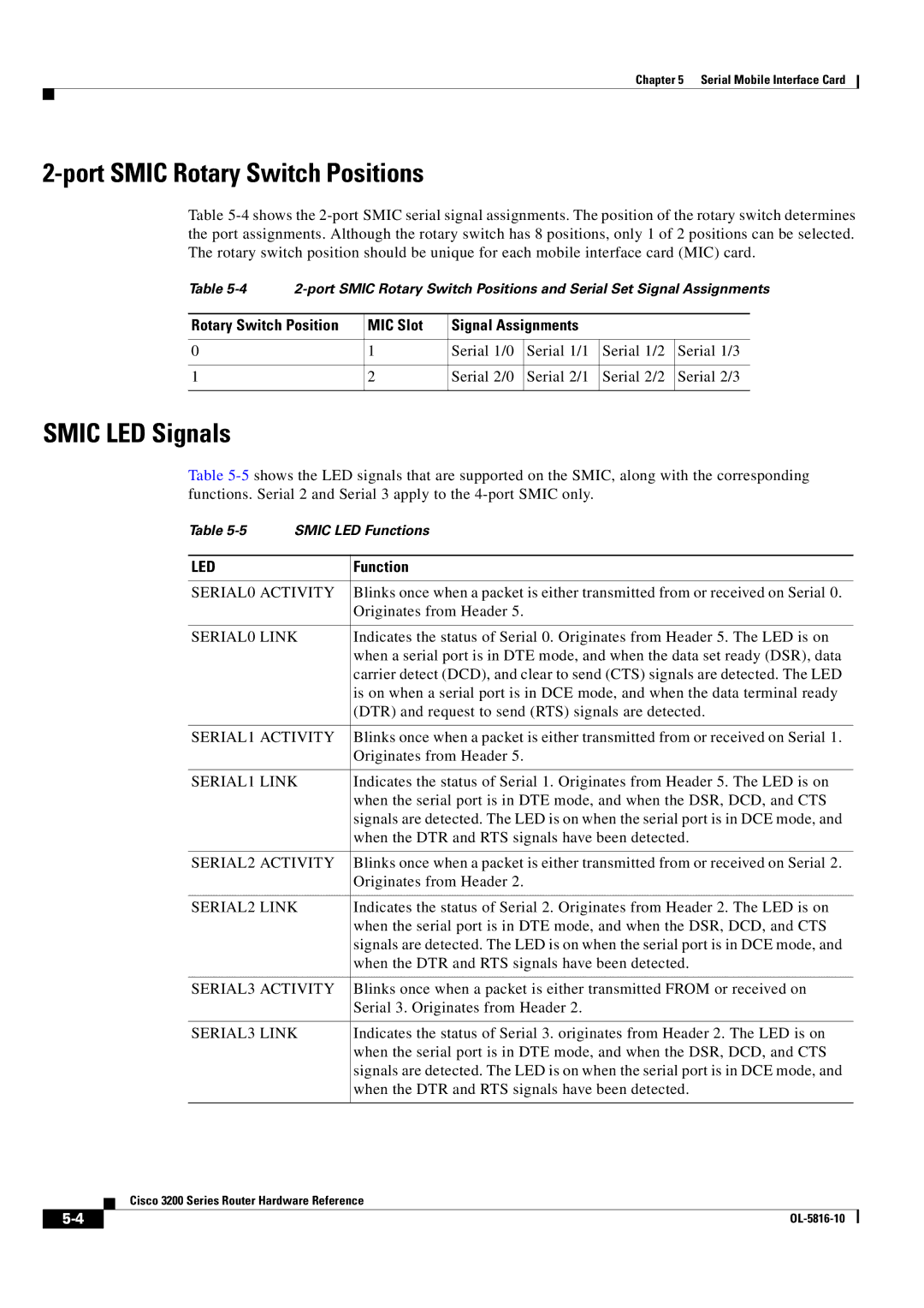
Table 5-4 shows the 2-port SMIC serial signal assignments. The position of the rotary switch determines the port assignments. Although the rotary switch has 8 positions, only 1 of 2 positions can be selected. The rotary switch position should be unique for each mobile interface card (MIC) card.

Table 5-4

2-port SMIC Rotary Switch Positions and Serial Set Signal Assignments


Rotary Switch Position

MIC Slot

Signal Assignments


0


1

Serial 1/0

Serial 1/1

Serial 1/2

Serial 1/3


1


2

Serial 2/0

Serial 2/1

Serial 2/2

Serial 2/3


SMIC LED Signals

Table 5-5shows the LED signals that are supported on the SMIC, along with the corresponding functions. Serial 2 and Serial 3 apply to the 4-port SMIC only.

Table 5-5 SMIC LED Functions

LED

Function


SERIAL0 ACTIVITY

Blinks once when a packet is either transmitted from or received on Serial 0.


Originates from Header 5.


SERIAL0 LINK

Indicates the status of Serial 0. Originates from Header 5. The LED is on


when a serial port is in DTE mode, and when the data set ready (DSR), data


carrier detect (DCD), and clear to send (CTS) signals are detected. The LED


is on when a serial port is in DCE mode, and when the data terminal ready


(DTR) and request to send (RTS) signals are detected.


SERIAL1 ACTIVITY

Blinks once when a packet is either transmitted from or received on Serial 1.


Originates from Header 5.


SERIAL1 LINK

Indicates the status of Serial 1. Originates from Header 5. The LED is on


when the serial port is in DTE mode, and when the DSR, DCD, and CTS


signals are detected. The LED is on when the serial port is in DCE mode, and


when the DTR and RTS signals have been detected.


SERIAL2 ACTIVITY

Blinks once when a packet is either transmitted from or received on Serial 2.


Originates from Header 2.


SERIAL2 LINK

Indicates the status of Serial 2. Originates from Header 2. The LED is on


when the serial port is in DTE mode, and when the DSR, DCD, and CTS


signals are detected. The LED is on when the serial port is in DCE mode, and


when the DTR and RTS signals have been detected.


SERIAL3 ACTIVITY

Blinks once when a packet is either transmitted FROM or received on


Serial 3. Originates from Header 2.


SERIAL3 LINK

Indicates the status of Serial 3. originates from Header 2. The LED is on


when the serial port is in DTE mode, and when the DSR, DCD, and CTS


signals are detected. The LED is on when the serial port is in DCE mode, and


when the DTR and RTS signals have been detected.


Cisco 3200 Series Router Hardware Reference

5-4

OL-5816-10


Page 58
Image 58
Cisco Systems 3200 manual Smic LED Signals, SERIAL0 Activity

3200 specifications

Cisco Systems 3200 Series routers are designed to deliver high-performance, reliable networking solutions for enterprise and service provider environments. They are part of Cisco's extensive portfolio that addresses the challenges of modern networking, particularly in connecting remote offices and branch locations efficiently and securely.

One of the standout features of the Cisco 3200 Series is its scalability. The routers support a variety of modular interfaces, allowing organizations to tailor their network infrastructure according to specific needs. This modularity ensures that as businesses grow and their networking requirements evolve, the Cisco 3200 can adapt without necessitating a complete overhaul of existing hardware.

Security is another critical characteristic of the Cisco 3200 routers. They incorporate robust security features such as integrated firewall capabilities, advanced encryption standards, and Virtual Private Network (VPN) support. This ensures that sensitive data transmitted over the network is protected from potential threats, making them ideal for businesses that prioritize security, especially in regulated industries.

Performance-wise, the Cisco 3200 is equipped with advanced processing capabilities, enabling it to handle high data throughput even in demanding environments. This performance is bolstered by the use of Cisco's proprietary technologies, such as Quality of Service (QoS) and traffic shaping, which allow the prioritization of critical applications to ensure seamless connectivity.

The router series also benefits from Cisco's extensive software ecosystem, which includes Cisco IOS (Internetwork Operating System). IOS provides a familiar interface for network administrators, alongside a wealth of features for configuration and management. Furthermore, the Cisco 3200 Series is designed to integrate with Cisco's Application Policy Infrastructure Controller (APIC) and Software-Defined Networking (SDN) solutions, offering enhanced flexibility in managing network resources.

Connectivity options for the Cisco 3200 Series are extensive, offering support for various WAN technologies, including MPLS, LTE, and broadband internet. This versatility enables organizations to choose the best connectivity solutions according to their geographic and operational requirements.

Finally, the Cisco 3200 Series routers are built with reliability in mind. They are designed for high availability and redundancy, ensuring that network services remain uninterrupted in the event of hardware failures or maintenance activities.

In conclusion, Cisco Systems 3200 routers represent a comprehensive networking solution, combining scalability, security, performance, and reliability, making them a preferred choice for organizations looking to enhance their networking infrastructure in a dynamic digital landscape.