3750-E, 3560-E specifications
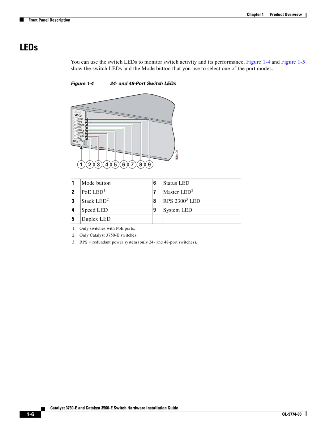
Cisco Systems RPS (Redundant Power System) 2300, along with the 3750-E and 3560-E series switches, represents a significant technological advancement in enterprise networking. These devices are designed to enhance network reliability, scalability, and efficiency, making them integral components in modern enterprise infrastructures.The Cisco RPS 2300 is designed to provide redundant power to specified Cisco switches, ensuring continuous operation during power disruptions. This system can support up to six devices, enhancing power reliability and reducing downtime. The modularity of the RPS 2300 contributes to its flexibility, allowing enterprises to customize their power solutions to suit their networking needs. It features dual power input, which provides an additional layer of failover capability, ensuring that even in the event of a primary power failure, the backup power system can take over seamlessly.
On the other hand, the Cisco 3750-E series switches are enterprise-class devices that offer a rich feature set to support advanced network functions. These switches come with Cisco’s StackWise technology, enabling users to stack up to nine switches in a single logical unit. This increases port density and simplifies network management. The 3750-E also supports Power over Ethernet (PoE), allowing the delivery of power directly to devices like IP phones and access points through the networking cables. The switch is equipped with high-performance Layer 3 routing capabilities, providing enhanced IP routing options for enterprise networks.
The Cisco 3560-E series switches share many of the advanced features found in the 3750-E models but focus more on providing comprehensive Layer 2 and Layer 3 capabilities in a compact design. The 3560-E series supports Cisco’s advanced security features, such as dynamic VLAN assignment and security group access control lists (ACLs). Additionally, these switches support IPv6, preparing enterprise networks for future growth and addressing requirements.
Both the 3750-E and 3560-E are equipped with energy-efficient technologies, including intelligent power management and support for Energy Efficient Ethernet (EEE), helping organizations reduce their environmental footprint and operating costs. The integration of Cisco’s robust IOS software ensures that these devices are equipped with the latest features, ensuring strong performance, security, and scalability.
In summary, Cisco's RPS 2300, 3750-E, and 3560-E series exemplify the company's commitment to delivering cutting-edge networking solutions that meet the demands of modern enterprises, focusing on reliability, advanced features, and energy efficiency.

