9Connect the Power and Turn On the Router
Follow these steps to connect power to the Cisco 811 or 813 router and turn it on.
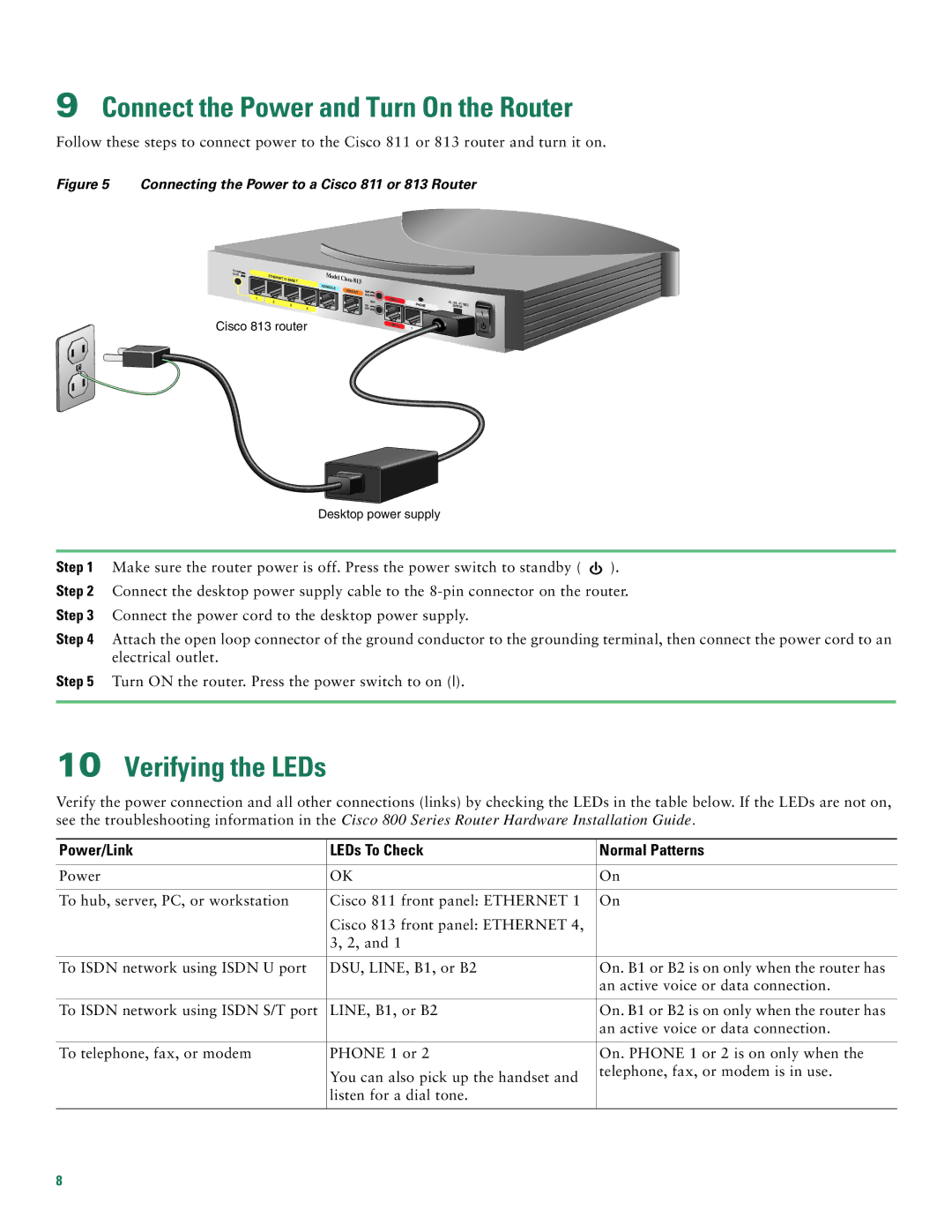
Figure 5 Connecting the Power to a Cisco 811 or 813 Router
TO HUB |
|
|
TO PC | ETHERNET 10 |
|
| BASE T | |
|
| |
| 1 |
|
| 2 | 3 |
|
|
4
Cisco 813 router
Model Cisco 813 CONSOLE ![]() ISDN S/T
ISDN S/T
NOR![]() RVS
RVS ![]()
DSU
ON OFF ![]()
ISDN U |
| +5, - |
| |
| PHONE | 24, | VDC | |
|
|
| ||
ISDN U | 1 |
|
|
|
| 2 |
|
| |
|
|
|
|
Desktop power supply
Step 1 | Make sure the router power is off. Press the power switch to standby ( |
| ). |
| |||
| |||
Step 2 Connect the desktop power supply cable to the | |||
Step 3 | Connect the power cord to the desktop power supply. |
|
|
Step 4 | Attach the open loop connector of the ground conductor to the grounding terminal, then connect the power cord to an | ||
| electrical outlet. |
|
|
Step 5 | Turn ON the router. Press the power switch to on (). |
|
|
|
|
|
|
10Verifying the LEDs
Verify the power connection and all other connections (links) by checking the LEDs in the table below. If the LEDs are not on, see the troubleshooting information in the Cisco 800 Series Router Hardware Installation Guide.
Power/Link | LEDs To Check | Normal Patterns |
|
|
|
Power | OK | On |
|
|
|
To hub, server, PC, or workstation | Cisco 811 front panel: ETHERNET 1 | On |
| Cisco 813 front panel: ETHERNET 4, |
|
| 3, 2, and 1 |
|
|
|
|
To ISDN network using ISDN U port | DSU, LINE, B1, or B2 | On. B1 or B2 is on only when the router has |
|
| an active voice or data connection. |
|
|
|
To ISDN network using ISDN S/T port | LINE, B1, or B2 | On. B1 or B2 is on only when the router has |
|
| an active voice or data connection. |
|
|
|
To telephone, fax, or modem | PHONE 1 or 2 | On. PHONE 1 or 2 is on only when the |
| You can also pick up the handset and | telephone, fax, or modem is in use. |
|
| |
| listen for a dial tone. |
|
|
|
|
8