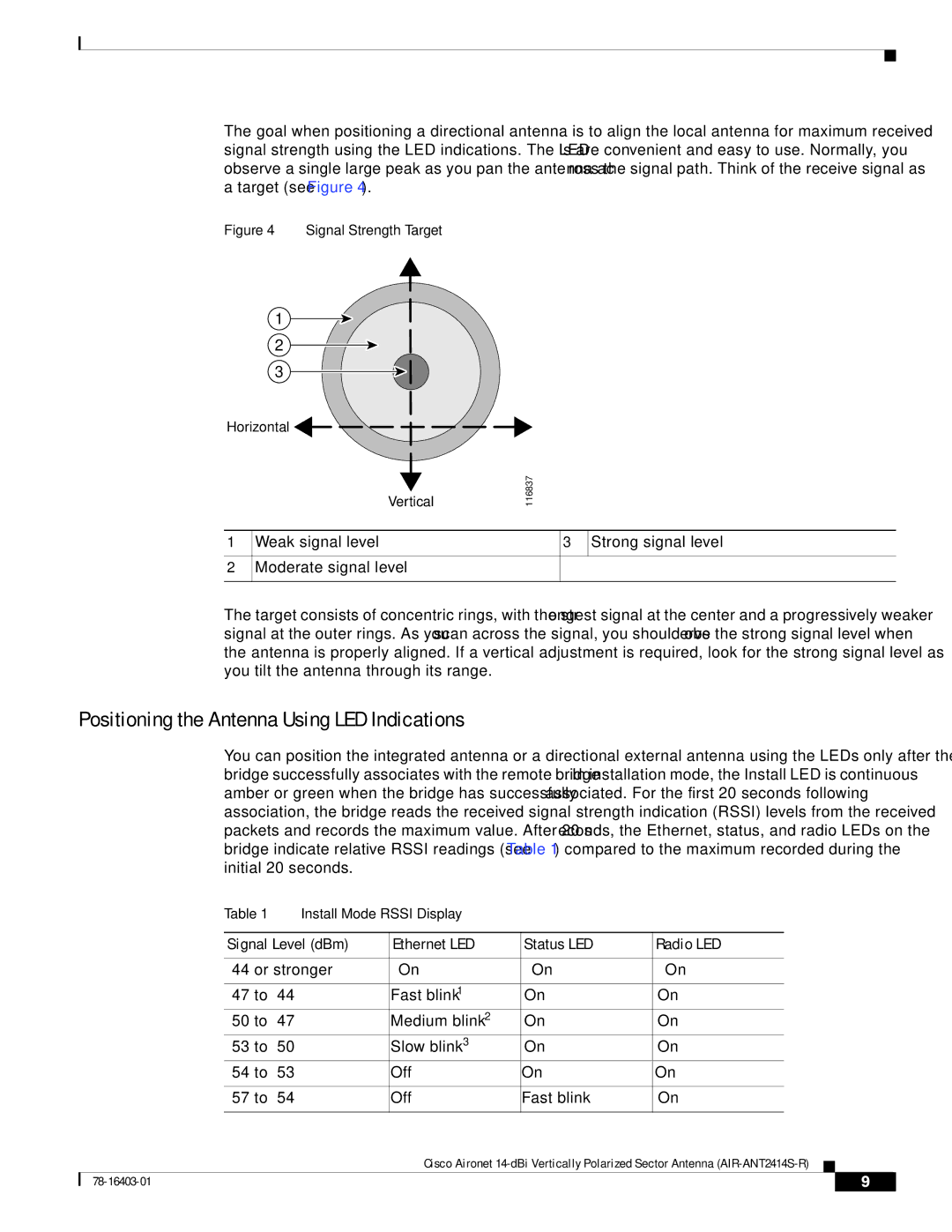
The goal when positioning a directional antenna is to align the local antenna for maximum received signal strength using the LED indications. The LEDs are convenient and easy to use. Normally, you observe a single large peak as you pan the antenna across the signal path. Think of the receive signal as a target (see Figure 4).
Figure 4 Signal Strength Target
1
2
3
Horizontal![]()
Vertical
1Weak signal level
2Moderate signal level
116837
3Strong signal level
The target consists of concentric rings, with the strongest signal at the center and a progressively weaker signal at the outer rings. As you scan across the signal, you should observe the strong signal level when the antenna is properly aligned. If a vertical adjustment is required, look for the strong signal level as you tilt the antenna through its range.
Positioning the Antenna Using LED Indications
You can position the integrated antenna or a directional external antenna using the LEDs only after the bridge successfully associates with the remote bridge. In installation mode, the Install LED is continuous amber or green when the bridge has successfully associated. For the first 20 seconds following association, the bridge reads the received signal strength indication (RSSI) levels from the received packets and records the maximum value. After 20 seconds, the Ethernet, status, and radio LEDs on the bridge indicate relative RSSI readings (see Table 1) compared to the maximum recorded during the initial 20 seconds.
|
| Table 1 | Install Mode RSSI Display |
|
|
|
|
|
| |
|
|
|
|
|
|
| ||||
|
| Signal Level (dBm) | Ethernet LED | Status LED | Radio LED | |||||
|
|
|
|
|
|
| ||||
|
| On | On | On | ||||||
|
|
|
|
|
|
|
| |||
|
|
| Fast blink1 | On | On |
| ||||
|
|
| Medium blink2 | On | On |
| ||||
|
|
| Slow blink3 | On | On |
| ||||
|
|
| Off | On | On | |||||
|
|
|
|
|
|
|
| |||
|
|
| Off | Fast blink | On | |||||
|
|
|
|
|
|
|
|
|
|
|
|
|
|
| Cisco Aironet |
|
|
| |||
|
|
|
|
| ||||||
|
|
|
|
|
|
|
|
|
|
|
|
|
|
|
|
|
|
| 9 |
| |
|
|
|
|
|
|
|
| |||