ASR1000 specifications
The Cisco ASR 1000 Series Aggregation Services Routers are designed to meet the needs of enterprises and service providers seeking high-performance networking solutions. With a combination of scalability, reliability, and security, these routers provide an ideal platform for delivering a wide range of services in a compact form factor.One of the standout features of the ASR 1000 is its embedded hardware architecture. It utilizes a unique Distributed Services Architecture that allows for greater resource allocation and management, resulting in enhanced performance across various applications. This architecture enables the router to dynamically balance workloads across multiple CPUs, ensuring optimal resource utilization and reducing latency.
The ASR 1000 Series supports a variety of interfaces, including Ethernet, T1/E1, and T3/E3, making it highly versatile for different connectivity options. With support for up to 200 Gbps of throughput, it can handle the growing demands of modern networks, including video conferencing, cloud applications, and data-intensive services.
Security is a paramount feature of the ASR 1000. The routers come equipped with advanced security technologies such as Cisco IOS XE software, which includes built-in encryption and secure access controls. This ensures that data remains protected in transit, allowing organizations to safeguard sensitive information while maintaining compliance with industry regulations.
Another key characteristic of the ASR 1000 is its modularity. Users can easily add or upgrade services through service modules and network interface modules, providing the flexibility needed to adapt to changing network requirements. This modular approach not only helps in managing costs but also extends the life cycle of the hardware.
In terms of manageability, the ASR 1000 Series incorporates Cisco’s Intelligent Network Services, providing comprehensive monitoring and troubleshooting capabilities. This allows network administrators to gain insights into network performance, optimize service delivery, and promptly address any issues that arise.
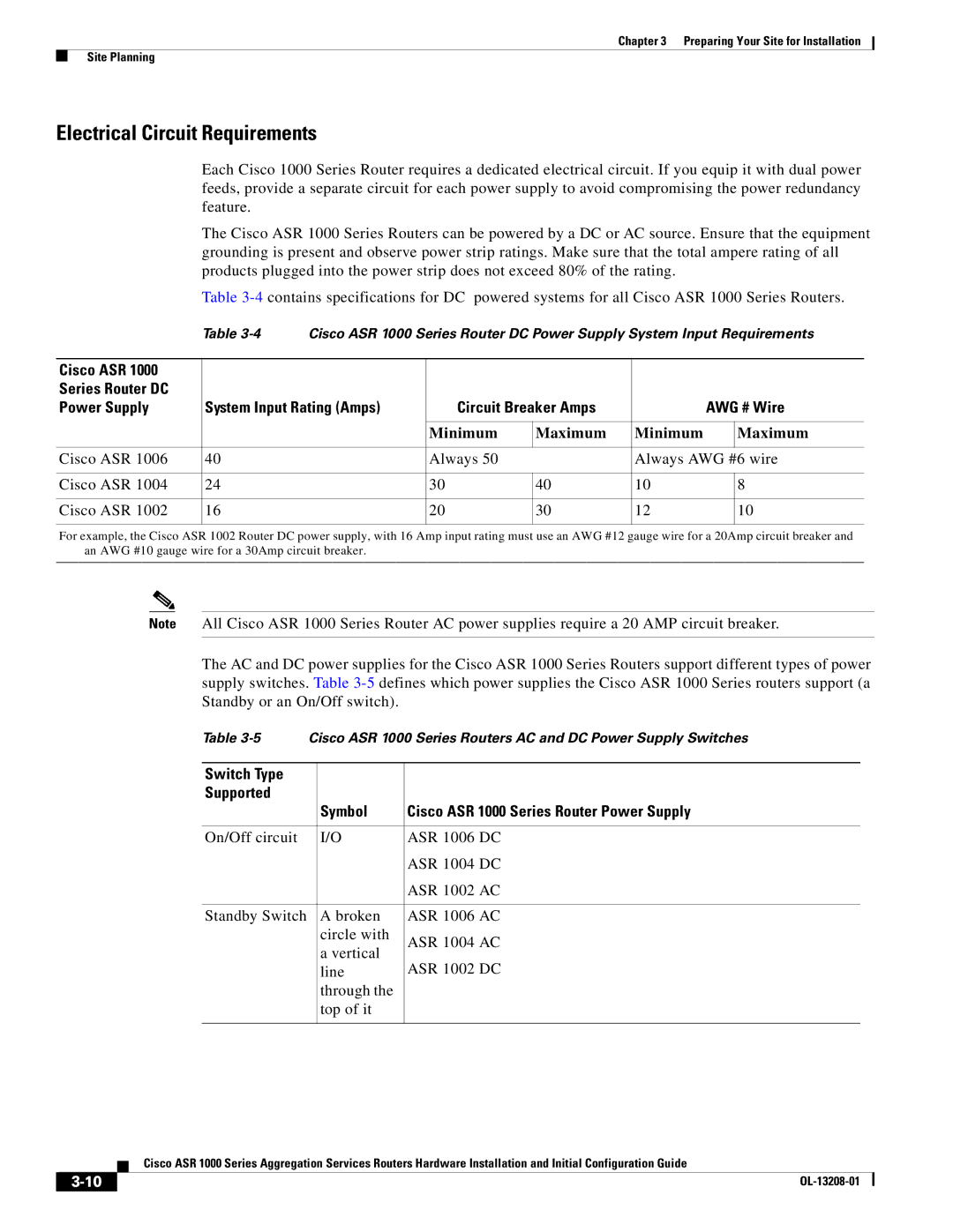
Finally, the ASR 1000 routers are designed for high availability, featuring redundant power supplies and fans. Coupled with advanced routing protocols and features such as Cisco’s Continuous Availability, the ASR 1000 ensures minimal downtime and uninterrupted service delivery.
In conclusion, the Cisco ASR 1000 Series Aggregation Services Routers combine performance, scalability, security, and manageability, making them an excellent choice for organizations looking to modernize their networking infrastructure while efficiently handling the demands of contemporary applications. Whether for enterprise networks or service provider environments, the ASR 1000 provides a robust and future-proof solution.

