Linksys DPC3008/EPC3008
Understanding the Front Panel Indicators
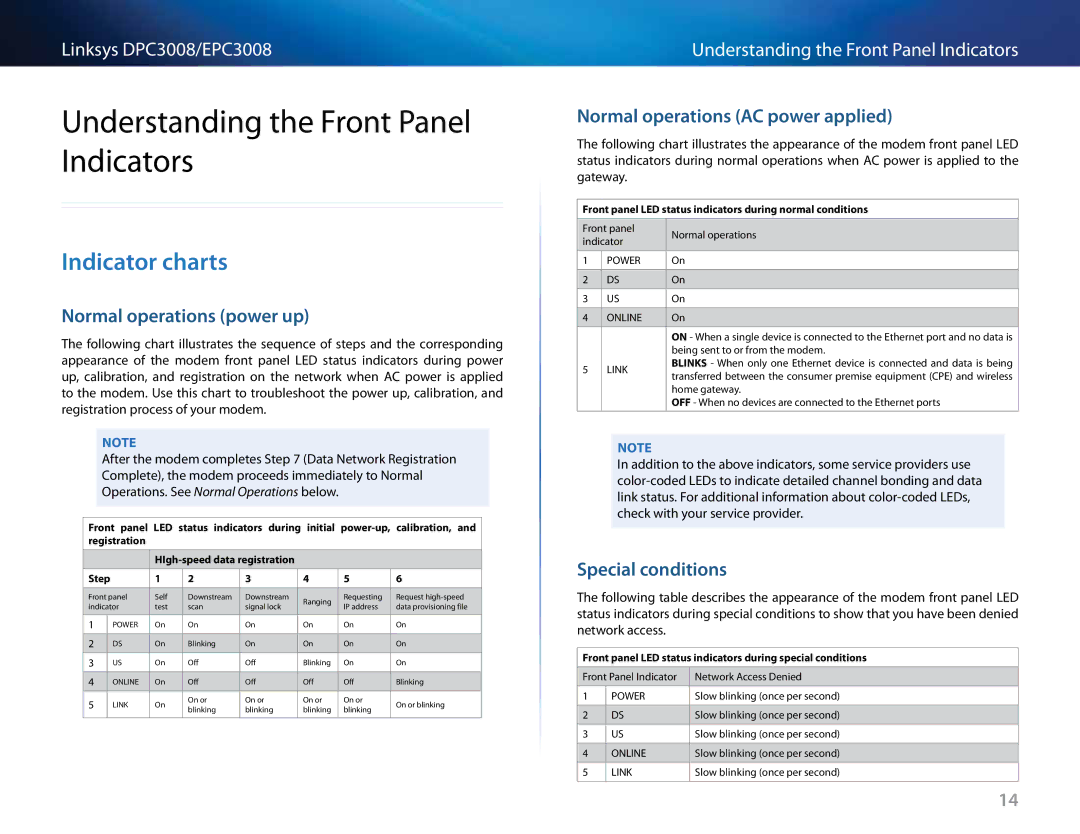
Indicator charts
Normal operations (power up)
The following chart illustrates the sequence of steps and the corresponding appearance of the modem front panel LED status indicators during power up, calibration, and registration on the network when AC power is applied to the modem.. Use this chart to troubleshoot the power up, calibration, and registration process of your modem..
Note
After the modem completes Step 7 (Data Network Registration Complete), the modem proceeds immediately to Normal Operations.. See Normal Operations below..
Front panel LED status indicators during initial
Step |
| 1 | 2 | 3 | 4 | 5 | 6 | ||
|
|
|
|
|
|
|
| ||
Front panel | Self | Downstream | Downstream | Ranging | Requesting | Request | |||
indicator | test | scan | signal lock | IP address | data provisioning file | ||||
| |||||||||
|
|
|
|
|
|
|
|
| |
1 |
| POWER | On | On | On | On | On | On | |
|
|
|
|
|
|
|
|
| |
2 |
| DS | On | Blinking | On | On | On | On | |
|
|
|
|
|
|
|
|
| |
3 |
| US | On | Off | Off | Blinking | On | On | |
|
|
|
|
|
|
|
|
| |
4 |
| ONLINE | On | Off | Off | Off | Off | Blinking | |
|
|
|
|
|
|
|
|
| |
5 |
| LINK | On | On or | On or | On or | On or | On or blinking | |
| blinking | blinking | blinking | blinking | |||||
|
|
|
|
| |||||
|
|
|
|
|
|
|
|
| |
Understanding the Front Panel Indicators
Normal operations (AC power applied)
The following chart illustrates the appearance of the modem front panel LED status indicators during normal operations when AC power is applied to the gateway..
Front panel LED status indicators during normal conditions | |||
|
|
| |
Front panel | Normal operations | ||
indicator | |||
| |||
|
|
| |
1 | POWER | On | |
|
|
| |
2 | DS | On | |
|
|
| |
3 | US | On | |
|
|
| |
4 | ONLINE | On | |
|
|
| |
|
| ON - When a single device is connected to the Ethernet port and no data is | |
|
| being sent to or from the modem.. | |
5 | LINK | BLINKS - When only one Ethernet device is connected and data is being | |
transferred between the consumer premise equipment (CPE) and wireless | |||
|
| ||
|
| home gateway.. | |
|
| OFF - When no devices are connected to the Ethernet ports | |
|
|
| |
Note
In addition to the above indicators, some service providers use
Special conditions
The following table describes the appearance of the modem front panel LED status indicators during special conditions to show that you have been denied network access..
Front panel LED status indicators during special conditions
Front Panel Indicator | Network Access Denied | |
|
|
|
1 | POWER | Slow blinking (once per second) |
|
|
|
2 | DS | Slow blinking (once per second) |
|
|
|
3 | US | Slow blinking (once per second) |
|
|
|
4 | ONLINE | Slow blinking (once per second) |
|
|
|
5 | LINK | Slow blinking (once per second) |
|
|
|
14