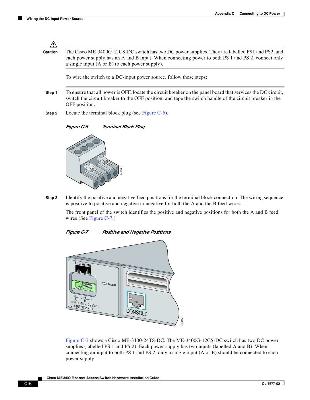
ME 3400 specifications
Cisco Systems ME 3400 Series is a robust family of Ethernet access switches designed specifically for service provider environments. These switches are engineered to deliver excellent performance, reliability, and flexibility, making them ideal for deploying Layer 2 and Layer 3 services to residential and business customers.One of the prominent features of the ME 3400 series is its support for advanced Ethernet technologies. It provides extensive support for both traditional and modern Ethernet services, including Carrier Ethernet. With features such as Ethernet Operations, Administration, and Maintenance (EOAM), the ME 3400 aids in managing network performance and troubleshooting issues effectively. This capability ensures that service providers can deliver high-quality services and maintain optimal network health.
The ME 3400 series includes various models that support a range of port configurations, enabling scalability and adaptability to different network needs. This includes support for both Fast Ethernet and Gigabit Ethernet interfaces. The switches can accommodate multiple speed configurations, making them versatile for diverse deployment scenarios, from small businesses to large enterprise networks.
Another key characteristic of the ME 3400 is its integrated support for resilient Ethernet technologies, such as EtherChannel, Spanning Tree Protocol (STP), and Rapid Spanning Tree Protocol (RSTP). These technologies enhance redundancy and improve network reliability, crucial for service providers who require minimal downtime and high service availability.
Security is a top priority for service providers, and the ME 3400 series addresses this with extensive security features. It supports VLANs for traffic segmentation, access control lists (ACLs) for traffic filtering, and DHCP snooping to prevent unauthorized access to the network. These security measures ensure that both consumer and enterprise traffic remains isolated and secure.
Additionally, the ME 3400 series supports IPv4 and IPv6 routing, offering flexibility for service providers to cater to a broad customer base. The ability to manage both protocols ensures that networks can evolve seamlessly as internet traffic transitions to IPv6.
With energy efficiency increasingly becoming a concern, Cisco has integrated power-saving features into the ME 3400 series. These switches support Energy Efficient Ethernet (EEE) technology, which reduces power consumption during periods of low traffic, helping service providers to reduce operational costs.
In summary, the Cisco ME 3400 series is a versatile platform rich in features that streamline service delivery while ensuring high performance, security, and energy efficiency. It is an ideal choice for service providers looking to enhance their Ethernet services and meet evolving customer demands.


