Chapter 1 About Cisco IP Solution Center
The Customer’s and Provider’s View of the Network
A
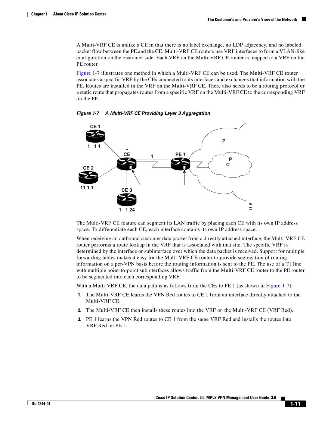
Figure 1-7 illustrates one method in which a Multi-VRF CE can be used. The Multi-VRF CE router associates a specific VRF by the CEs connected to its interfaces and exchanges that information with the PE. Routes are installed in the VRF on the Multi-VRF CE. There also needs to be a routing protocol or a static route that propagates routes from a specific VRF on the Multi-VRF CE to the corresponding VRF on the PE.
Figure 1-7 A Multi-VRF CE Providing Layer 3 Aggregation
CE 1 |
|
|
|
|
|
|
|
|
|
|
|
|
|
|
|
|
|
| Service |
10.1/16 |
|
|
|
|
|
|
|
| Provider |
|
|
|
|
| Network | ||||
|
| PE 1 | |||||||
| CE | T1 line | |||||||
|
|
|
|
|
|
|
| MPLS | |
|
|
|
|
|
|
|
|
| |
CE 2 |
|
|
|
|
|
|
|
| Core |
|
|
|
|
|
|
| |||
|
|
|
|
|
|
|
| Network | |
|
|
|
|
|
|
|
| ||
11.1/16 |
|
|
|
|
|
|
|
| |
|
|
|
|
|
| ||||
CE 3 | VRF Red | VRF Red | |||||||
|
|
|
|
|
|
| |||
| 10.1/24 |
|
|
|
|
|
| ||
93165
The
When receiving an outbound customer data packet from a directly attached interface, the
With a
1.The
2.The
3.PE 1 learns the VPN Red routes to CE 1 from the same VRF Red and installs the routes into VRF Red on
Cisco IP Solution Center, 3.0: MPLS VPN Management User Guide, 3.0
|
| ||
|
|
