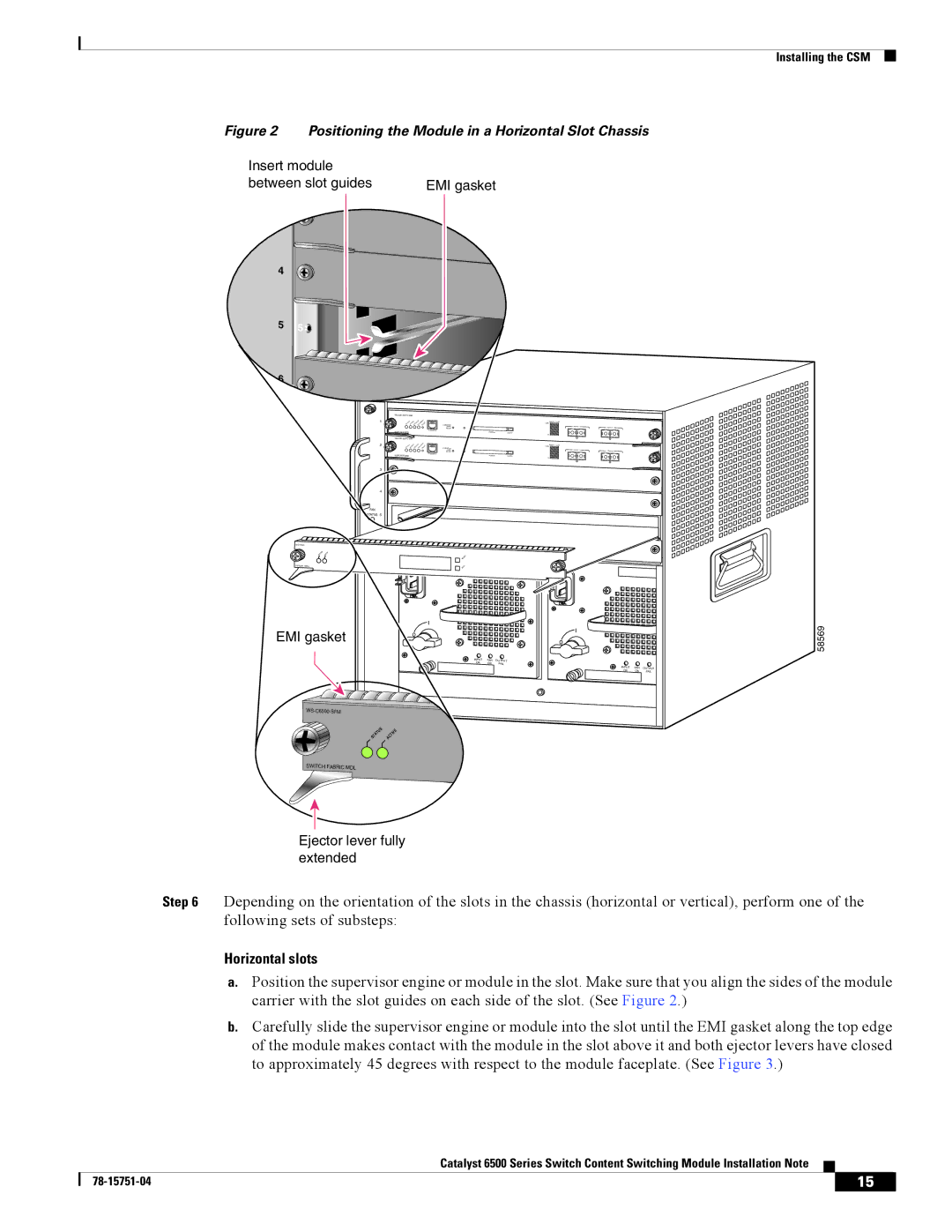
Figure 2 Positioning the Module in a Horizontal Slot Chassis
Insert module |
| |
between slot guides | EMI gasket | |
| 3 |
|
4 | 4 |
|
|
| |
5 | 5 |
|
|
| |
66![]()
|
|
|
|
| |
1 |
|
| Switch | Load |
|
CONSOLE |
| 100% | PORT 1 |
| |
| PORT |
|
| PORT 2 | |
| MODE |
|
|
| |
| CONSOLE |
|
|
|
|
| SUPERVISOR2 | PCMCIA | EJECT |
|
|
|
|
| 1% |
|
|
|
|
|
|
| |
2 |
|
| Switch | Load |
|
CONSOLE |
| 100% | PORT 1 |
| |
| PORT |
|
| PORT 2 | |
| MODE |
|
|
| |
| CONSOLE |
|
|
|
|
| SUPERVISOR2 | PCMCIA | EJECT |
|
|
|
|
| 1% |
|
|
3
4
FAN
STATUS 5
24 PORT 100FX
EMI gasket |
| o | o |
|
|
|
|
|
|
| |
|
| INPUT | FAN OUTPUT |
|
|
|
| OK | FAIL |
|
|
|
|
| INPUT | FAN | OUTPUT |
|
|
| OK | OK | FAIL |
|
|
|
|
| |
S |
| E |
|
|
|
TU |
| TIV |
|
|
|
TA | C |
|
|
| |
S | A |
|
|
|
|
SWITCH FABRIC MDL |
|
|
|
|
|
Installing the CSM
58569
Ejector lever fully extended
Step 6 Depending on the orientation of the slots in the chassis (horizontal or vertical), perform one of the following sets of substeps:
Horizontal slots
a.Position the supervisor engine or module in the slot. Make sure that you align the sides of the module carrier with the slot guides on each side of the slot. (See Figure 2.)
b.Carefully slide the supervisor engine or module into the slot until the EMI gasket along the top edge of the module makes contact with the module in the slot above it and both ejector levers have closed to approximately 45 degrees with respect to the module faceplate. (See Figure 3.)
Catalyst 6500 Series Switch Content Switching Module Installation Note
| 15 |
| |
|
|
