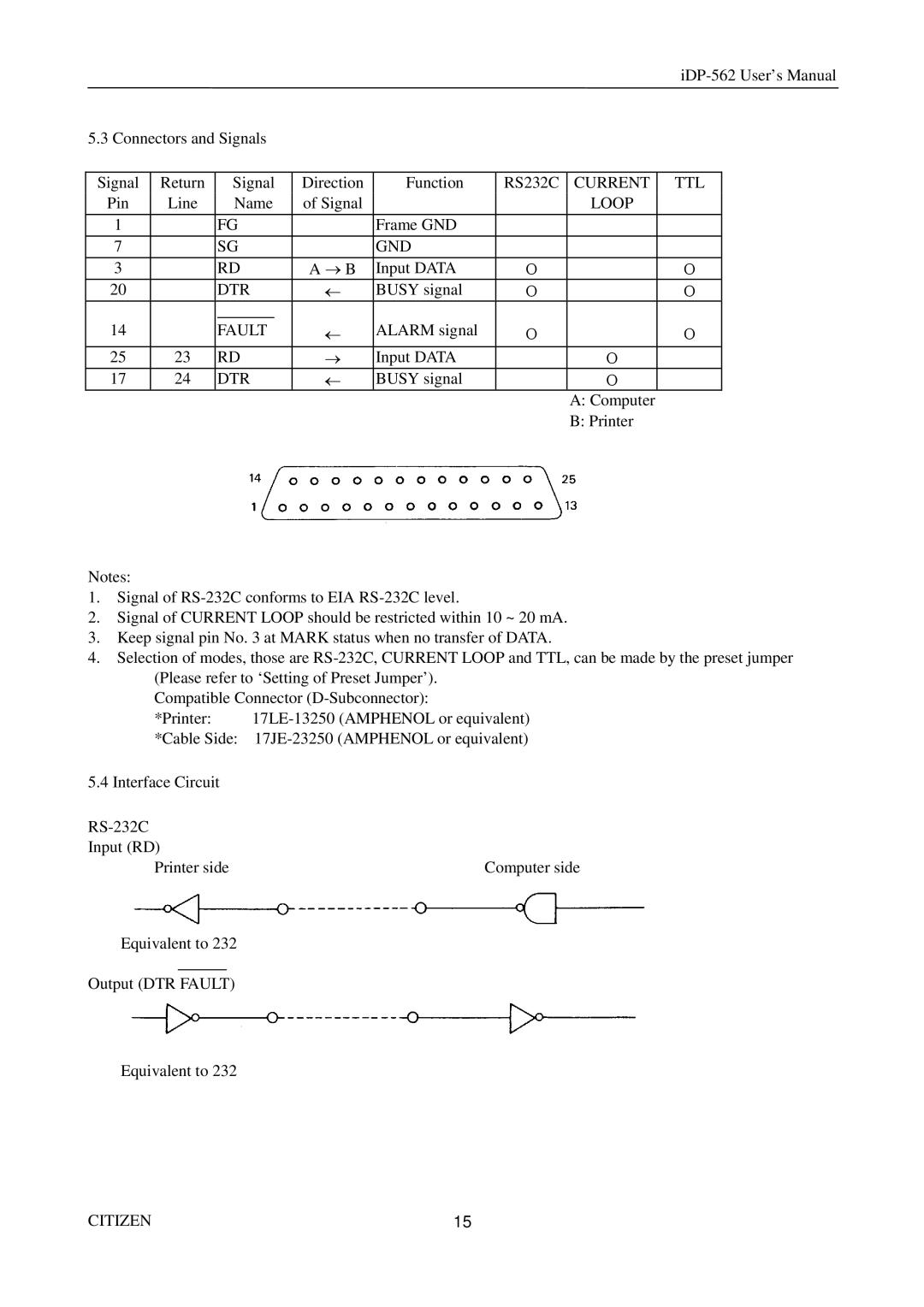
5.3 Connectors and Signals
Signal | Return | Signal | Direction | Function | RS232C | CURRENT | TTL | |
Pin | Line | Name | of Signal |
|
| LOOP |
| |
|
|
|
|
|
|
|
|
|
1 |
| FG |
| Frame GND |
|
|
| |
|
|
|
|
|
|
|
|
|
7 |
| SG |
| GND |
|
|
| |
3 |
| RD | A ® B | Input DATA | O |
| O | |
20 |
| DTR | ¬ | BUSY signal | O |
| O | |
|
|
|
|
|
|
|
|
|
14 |
| FAULT | ¬ | ALARM signal | O |
| O | |
|
|
|
|
|
|
|
| |
25 | 23 | RD | ® | Input DATA |
| O |
| |
17 | 24 | DTR | ¬ | BUSY signal |
| O |
| |
|
|
|
|
|
|
| A: Computer | |
|
|
|
|
|
|
| B: Printer | |
Notes:
1.Signal of
2.Signal of CURRENT LOOP should be restricted within 10 ~ 20 mA.
3.Keep signal pin No. 3 at MARK status when no transfer of DATA.
4.Selection of modes, those are
Compatible Connector
*Printer: | |
*Cable Side: | |
5.4 Interface Circuit |
|
| |
Input (RD) |
|
Printer side | Computer side |
Equivalent to 232
Output (DTR FAULT)
Equivalent to 232
CITIZEN | 15 |