Section VI Appendix (Continued)
ALTERNATE MICROPHONES AND INSTALLATION
For best results, the user should select a
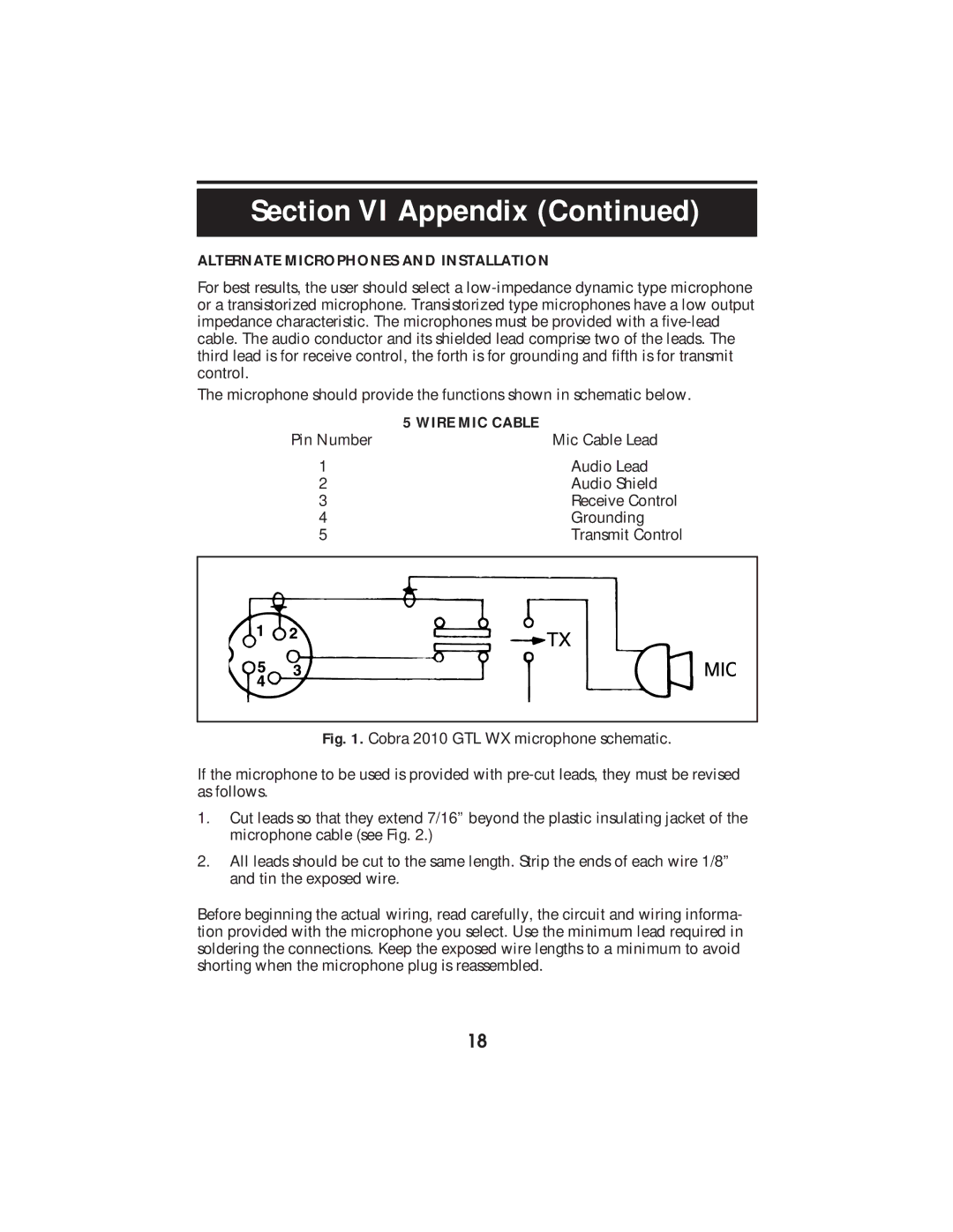
The microphone should provide the functions shown in schematic below.
| 5 WIRE MIC CABLE | |
Pin Number | Mic Cable Lead | |
1 | Audio Lead | |
2 | Audio Shield | |
3 | Receive Control | |
4 | Grounding | |
5 | Transmit Control | |
|
|
|
|
|
|
|
|
|
|
|
|
Fig. 1. Cobra 2010 GTL WX microphone schematic.
If the microphone to be used is provided with pre-cut leads, they must be revised as follows.
1.Cut leads so that they extend 7/16” beyond the plastic insulating jacket of the microphone cable (see Fig. 2.)
2.All leads should be cut to the same length. Strip the ends of each wire 1/8” and tin the exposed wire.
Before beginning the actual wiring, read carefully, the circuit and wiring informa- tion provided with the microphone you select. Use the minimum lead required in soldering the connections. Keep the exposed wire lengths to a minimum to avoid shorting when the microphone plug is reassembled.
18
