25 WX NW ST Manual 3.3 6/15/99 1:10 PM Page 4
| Installation | Installation |
|
|
| ||
|
|
|
|
Note
Connecting to an accessory fuse prevents the unit from being left on accidentally, and also per- mits operating the unit without running the engine.
Note
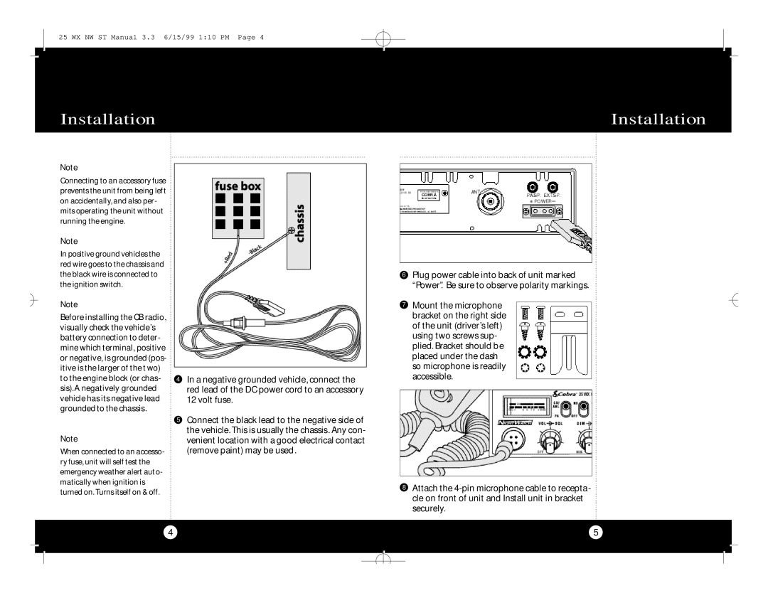
In positive ground vehicles the red wire goes to the chassis and the black wire is connected to the ignition switch.
Note
Before installing the CB radio, visually check the vehicle’s battery connection to deter- mine which terminal, positive or negative, is grounded (pos- itive is the larger of the two) to the engine block (or chas- sis).A negatively grounded vehicle has its negative lead grounded to the chassis.
Note
When connected to an accesso- ry fuse, unit will self test the emergency weather alert auto- matically when ignition is turned on. Turns itself on & off.
4In a negative grounded vehicle, connect the red lead of the DC power cord to an accessory 12 volt fuse.
5Connect the black lead to the negative side of the vehicle. This is usually the chassis. Any con- venient location with a good electrical contact (remove paint) may be used.
6Plug power cable into back of unit marked “Power”. Be sure to observe polarity markings.
7Mount the microphone bracket on the right side of the unit (driver’s left) using two screws sup- plied. Bracket should be placed under the dash so microphone is readily accessible.
8Attach the
4
5