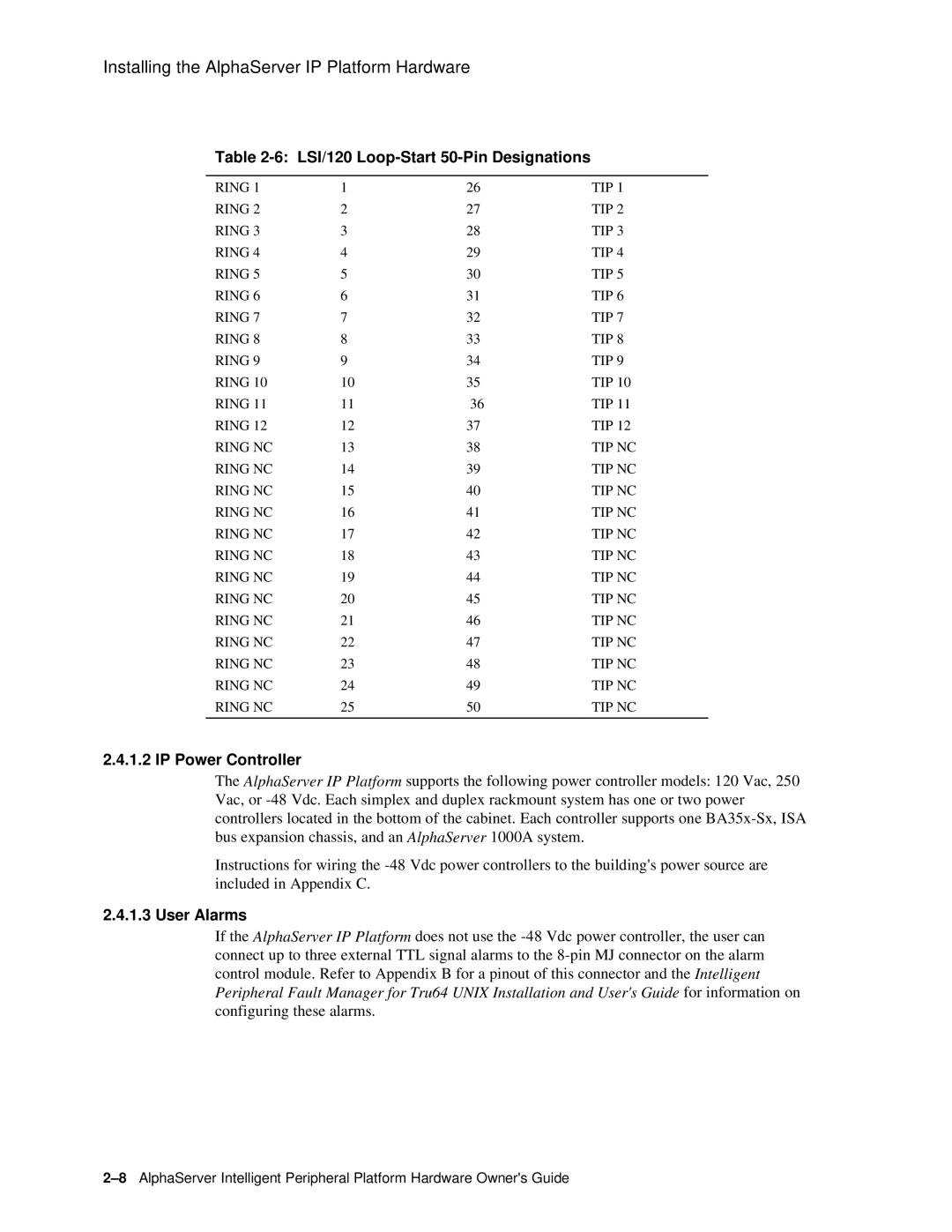
EK-ASIP2-OG. D01 specifications
The Compaq EK-ASIP2-OG. D01 is a significant product in the landscape of enterprise computing, featuring a range of capabilities that cater directly to the needs of businesses seeking high-performance solutions. This hardware is designed for a range of applications, offering a solid balance between efficiency and power, making it suitable for varying workloads.One of the key features of the EK-ASIP2-OG. D01 is its robust processing architecture. It is equipped with advanced microprocessor technology that ensures high-speed data processing and multitasking capabilities. This feature is particularly valuable in environments that require the simultaneous execution of multiple applications, thereby enhancing productivity and operational efficiency.
In addition to processing power, the EK-ASIP2-OG. D01 integrates significant memory capacity. This ensures that large applications can run smoothly without performance bottlenecks. The system supports scalable memory configurations, allowing users to optimize their setup according to their specific needs. This flexibility is essential for organizations that anticipate growth or require variable resource allocation.
Networking capabilities are another standout aspect of the EK-ASIP2-OG. D01. It comes with advanced network interfaces that promote seamless connectivity and high-speed data transfer. This is crucial for enterprise environments where data needs to be shared across various departments or locations in real time. The integration of leading networking technologies ensures reliable communication and collaboration, which are vital for modern business operations.
Furthermore, the EK-ASIP2-OG. D01 is designed with advanced security features, addressing the growing concerns around data protection. These features include encryption capabilities and secure access controls, ensuring that sensitive information remains safeguarded against potential threats. This focus on security makes it an ideal choice for businesses that prioritize safeguarding their data.
In terms of energy efficiency, the EK-ASIP2-OG. D01 employs power management technologies that reduce energy consumption without compromising performance. This not only contributes to cost savings for organizations but also aligns with sustainability goals, a factor increasingly important to businesses globally.
In conclusion, the Compaq EK-ASIP2-OG. D01 is a powerful and versatile server solution, equipped with cutting-edge technologies, robust security features, and sustainable energy practices. It is designed to meet the demands of modern enterprises, making it a reliable choice for businesses looking to enhance their computing capabilities and overall operational efficiency.
