WALL SWITCH / THERMOSTAT
For ease of accessibility, an optional remote wall switch or millivolt thermostat may be installed in a convenient location. Route
7
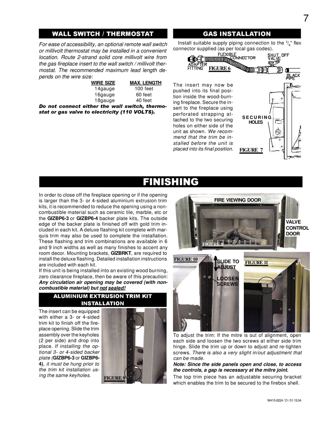
GAS INSTALLATION
Install suitable supply piping connection to the 3/8" flex connector supplied (as per local gas codes).
FIGURE 6
WIRE SIZE | MAX. LENGTH |
14gauge | 100 feet |
16gauge | 60 feet |
18gauge | 40 feet |
Do not connect either the wall switch, thermo- stat or gas valve to electricity (110 VOLTS).
The insert may now be pushed into its final posi- tion inside the
S E C U R I N G
HOLES
FIGURE 7
FINISHING
In order to close off the fireplace opening or if the opening is larger than the 3- or
If this unit is being installed into an existing wood burning, zero clearance fireplace, then be aware of this precaution:
Any circulation air opening may be covered (with non- combustible material) but not sealed!
ALUMINIUM EXTRUSION TRIM KIT
INSTALLATION
The insert can be equipped with either a 3- or
ing the same keyholes.
FIGURE 9
FIRE VIEWING DOOR
VALVE
CONTROL
DOOR
| FIGURE 8 |
FIGURE 10 | SLIDE TO FIGURE 11 |
| |
| ADJUST |
| LOOSEN |
| SCREWS |
To adjust the trim: If the mitre is out of alignment, open each side and loosen the two screws at either side trim hinge. Slide the trim up or down to adjust and
Note: Since the side panels open and close, to access the controls, a gap is necessary at the mitre joint.
The top trim piece has an adjustable securing bracket which enables the trim to be secured to the firebox shell.