11
ADJUSTMENTS
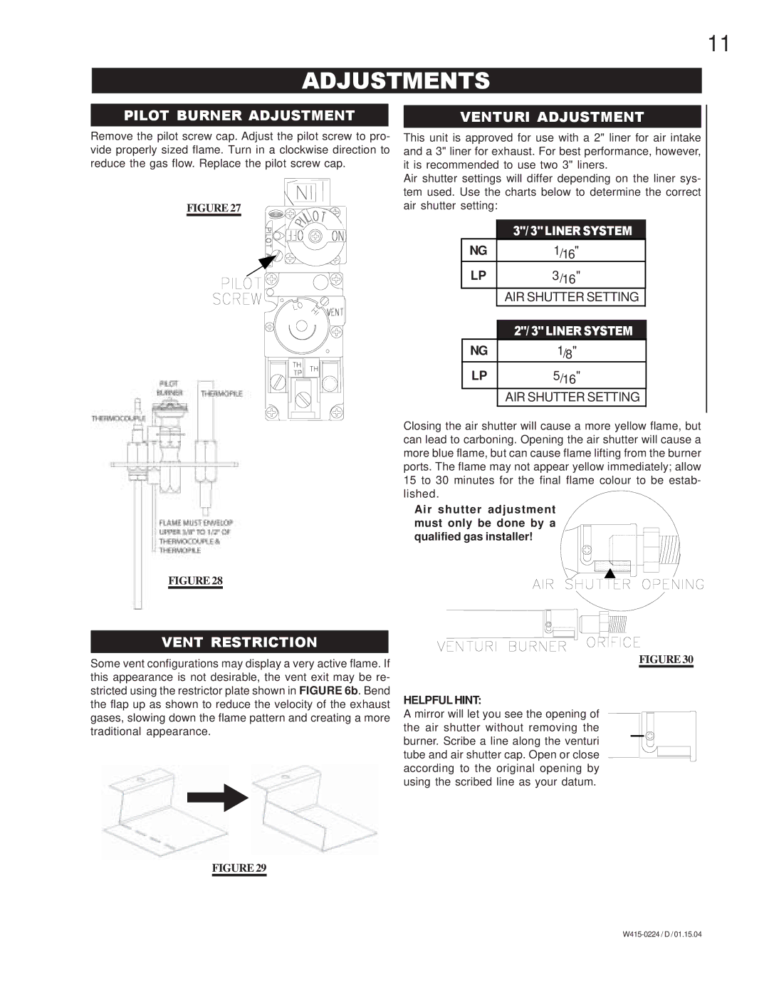
PILOT BURNER ADJUSTMENT
Remove the pilot screw cap. Adjust the pilot screw to pro- vide properly sized flame. Turn in a clockwise direction to reduce the gas flow. Replace the pilot screw cap.
FIGURE 27
FIGURE 28
VENT RESTRICTION
Some vent configurations may display a very active flame. If this appearance is not desirable, the vent exit may be re- stricted using the restrictor plate shown in FIGURE 6b. Bend the flap up as shown to reduce the velocity of the exhaust gases, slowing down the flame pattern and creating a more traditional appearance.
VENTURI ADJUSTMENT
This unit is approved for use with a 2" liner for air intake and a 3" liner for exhaust. For best performance, however, it is recommended to use two 3" liners.
Air shutter settings will differ depending on the liner sys- tem used. Use the charts below to determine the correct air shutter setting:
| 3"/3"LINERSYSTEM |
NG | 1/16" |
LP | 3/16" |
| AIR SHUTTER SETTING |
|
|
|
|
| 2"/3"LINERSYSTEM |
NG | 1/8" |
LP | 5/16" |
| AIR SHUTTER SETTING |
Closing the air shutter will cause a more yellow flame, but can lead to carboning. Opening the air shutter will cause a more blue flame, but can cause flame lifting from the burner ports. The flame may not appear yellow immediately; allow 15 to 30 minutes for the final flame colour to be estab- lished.
Air shutter adjustment must only be done by a qualified gas installer!
FIGURE 30
HELPFUL HINT:
A mirror will let you see the opening of the air shutter without removing the burner. Scribe a line along the venturi tube and air shutter cap. Open or close according to the original opening by using the scribed line as your datum.
FIGURE 29