CABLE SIZE
•All wiring should be in accordance with local standards.
•Before making any connection, check the electric power supply, it must have the same characteristics as what is displayed in the nameplate.
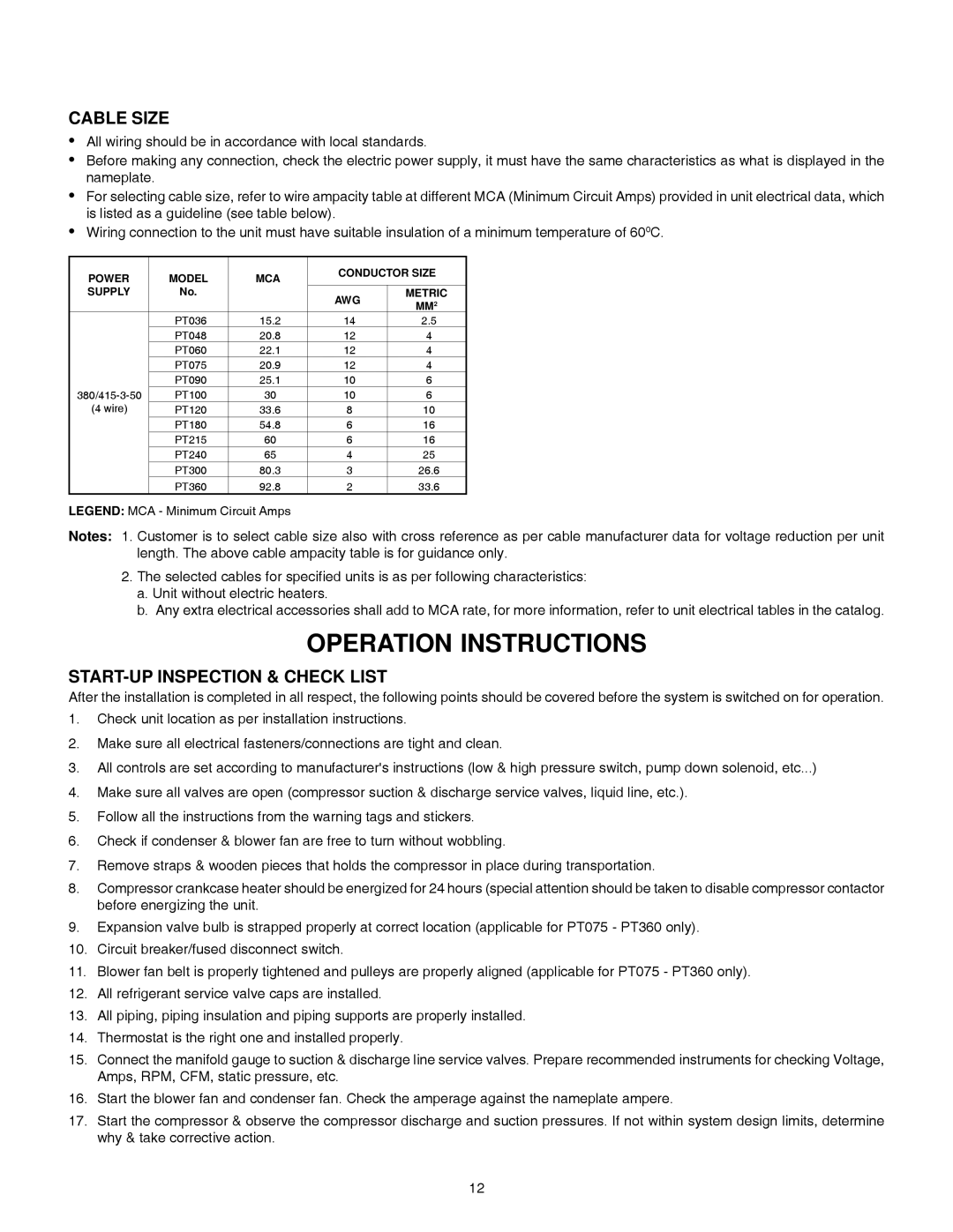
•For selecting cable size, refer to wire ampacity table at different MCA (Minimum Circuit Amps) provided in unit electrical data, which is listed as a guideline (see table below).
•Wiring connection to the unit must have suitable insulation of a minimum temperature of 600C.
POWER | MODEL | MCA | CONDUCTOR SIZE | |
|
| |||
SUPPLY | No. |
| AWG | METRIC |
|
|
| MM2 | |
| PT036 | 15.2 | 14 | 2.5 |
| PT048 | 20.8 | 12 | 4 |
| PT060 | 22.1 | 12 | 4 |
| PT075 | 20.9 | 12 | 4 |
| PT090 | 25.1 | 10 | 6 |
PT100 | 30 | 10 | 6 | |
(4 wire) | PT120 | 33.6 | 8 | 10 |
| PT180 | 54.8 | 6 | 16 |
| PT215 | 60 | 6 | 16 |
| PT240 | 65 | 4 | 25 |
| PT300 | 80.3 | 3 | 26.6 |
| PT360 | 92.8 | 2 | 33.6 |
LEGEND: MCA - Minimum Circuit Amps
Notes: 1. Customer is to select cable size also with cross reference as per cable manufacturer data for voltage reduction per unit length. The above cable ampacity table is for guidance only.
2.The selected cables for specified units is as per following characteristics:
a.Unit without electric heaters.
b.Any extra electrical accessories shall add to MCA rate, for more information, refer to unit electrical tables in the catalog.
OPERATION INSTRUCTIONS
START-UP INSPECTION & CHECK LIST
After the installation is completed in all respect, the following points should be covered before the system is switched on for operation.
1.Check unit location as per installation instructions.
2.Make sure all electrical fasteners/connections are tight and clean.
3.All controls are set according to manufacturer's instructions (low & high pressure switch, pump down solenoid, etc...)
4.Make sure all valves are open (compressor suction & discharge service valves, liquid line, etc.).
5.Follow all the instructions from the warning tags and stickers.
6.Check if condenser & blower fan are free to turn without wobbling.
7.Remove straps & wooden pieces that holds the compressor in place during transportation.
8.Compressor crankcase heater should be energized for 24 hours (special attention should be taken to disable compressor contactor before energizing the unit.
9.Expansion valve bulb is strapped properly at correct location (applicable for PT075 - PT360 only).
10.Circuit breaker/fused disconnect switch.
11.Blower fan belt is properly tightened and pulleys are properly aligned (applicable for PT075 - PT360 only).
12.All refrigerant service valve caps are installed.
13.All piping, piping insulation and piping supports are properly installed.
14.Thermostat is the right one and installed properly.
15.Connect the manifold gauge to suction & discharge line service valves. Prepare recommended instruments for checking Voltage, Amps, RPM, CFM, static pressure, etc.
16.Start the blower fan and condenser fan. Check the amperage against the nameplate ampere.
17.Start the compressor & observe the compressor discharge and suction pressures. If not within system design limits, determine why & take corrective action.
12