|
| Bussmann® | |
Bussmann® Power Module™ Switch |
| PS | |
|
|
| |
| How to configure Part Numbers: |
| |
| Step 1: Select Switch Amperage1 |
| |
| Power Module™ Switch |
|
|
| Rating (Amps) | Power Module Switch Catalog No. | |
| 30 | PS3 |
|
| 60 | PS6 |
|
| 100 | PS1 |
|
| 200 | PS2 |
|
400 | PS4 |
| |
|
|
| |
| Step 2: Select Options Needed5 |
| |
| Optional Accessories1 |
|
|
|
|
| Catalog |
|
| Rating | Number |
| Option 1 |
|
|
| Control Power Transformer | 208V | T20 |
| (CPT) Std. 100VA with PRI & | 240V | T24 |
| SEC Fuse (120V Secondary) | 480V | T48 |
|
| 600V | T60 |
| Option 2 |
|
|
| Fire Safety Interface | 24 Vdc Coil | R2 |
| Relay (3PDT, 10 amp, 120V) | 120 Vac Coil | R1 |
Option 3
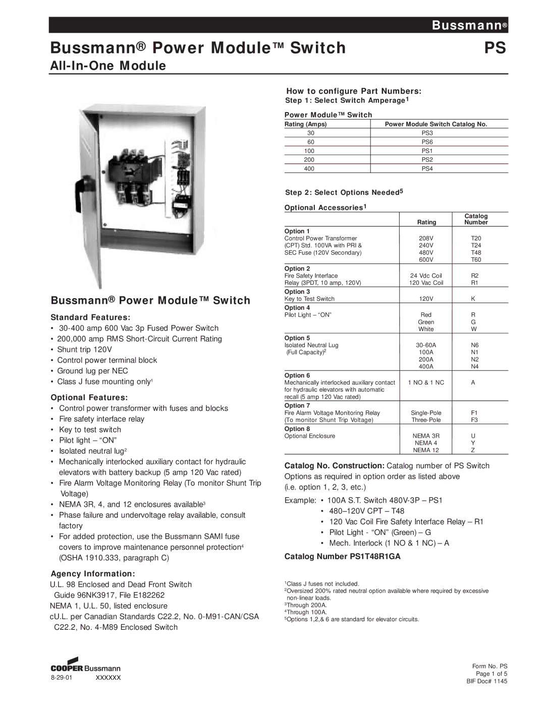
Bussmann® Power Module™ Switch
Standard Features:
•
•200,000 amp RMS
•Shunt trip 120V
•Control power terminal block
•Ground lug per NEC
•Class J fuse mounting only1
Optional Features:
•Control power transformer with fuses and blocks
•Fire safety interface relay
•Key to test switch
•Pilot light – “ON”
•Isolated neutral lug2
•Mechanically interlocked auxiliary contact for hydraulic elevators with battery backup (5 amp 120 Vac rated)
•Fire Alarm Voltage Monitoring Relay (To monitor Shunt Trip Voltage)
•NEMA 3R, 4, and 12 enclosures available3
•Phase failure and undervoltage relay available, consult factory
•For added protection, use the Bussmann SAMI fuse covers to improve maintenance personnel protection4 (OSHA 1910.333, paragraph C)
Agency Information:
U.L. 98 Enclosed and Dead Front Switch Guide 96NK3917, File E182262
NEMA 1, U.L. 50, listed enclosure
cU.L. per Canadian Standards C22.2, No.
Key to Test Switch | 120V | K |
Option 4 |
|
|
Pilot Light – “ON” | Red | R |
| Green | G |
| White | W |
Option 5 |
|
|
Isolated Neutral Lug | N6 | |
(Full Capacity)2 | 100A | N1 |
| 200A | N2 |
| 400A | N4 |
Option 6 |
|
|
Mechanically interlocked auxiliary contact | 1 NO & 1 NC | A |
for hydraulic elevators with automatic |
|
|
recall (5 amp 120 Vac rated) |
|
|
Option 7 |
|
|
Fire Alarm Voltage Monitoring Relay | F1 | |
(To monitor Shunt Trip Voltage) | F3 | |
Option 8 |
|
|
Optional Enclosure | NEMA 3R | U |
| NEMA 4 | Y |
| NEMA 12 | Z |
Catalog No. Construction: Catalog number of PS Switch Options as required in option order as listed above
(i.e. option 1, 2, 3, etc.)
Example: • 100A S.T. Switch
•
•120 Vac Coil Fire Safety Interface Relay – R1
•Pilot Light - “ON” (Green) – G
•Mech. Interlock (1 NO & 1 NC) – A
Catalog Number PS1T48R1GA
1Class J fuses not included.
2Oversized 200% rated neutral option available where required by excessive
3Through 200A.
4Through 100A.
5Options 1,2,& 6 are standard for elevator circuits.
|
| Form No. PS | |
XXXXXX | Page 1 of 5 | ||
BIF Doc# 1145 | |||
|
|