|
|
|
|
|
|
|
|
|
|
|
|
|
|
|
|
|
|
| Bussmann® | |||
Bussmann® Power Module™ Switch |
|
|
|
|
|
| PS | |||||||||||||||
|
|
|
|
|
|
|
|
|
|
|
|
|
|
|
|
|
| |||||
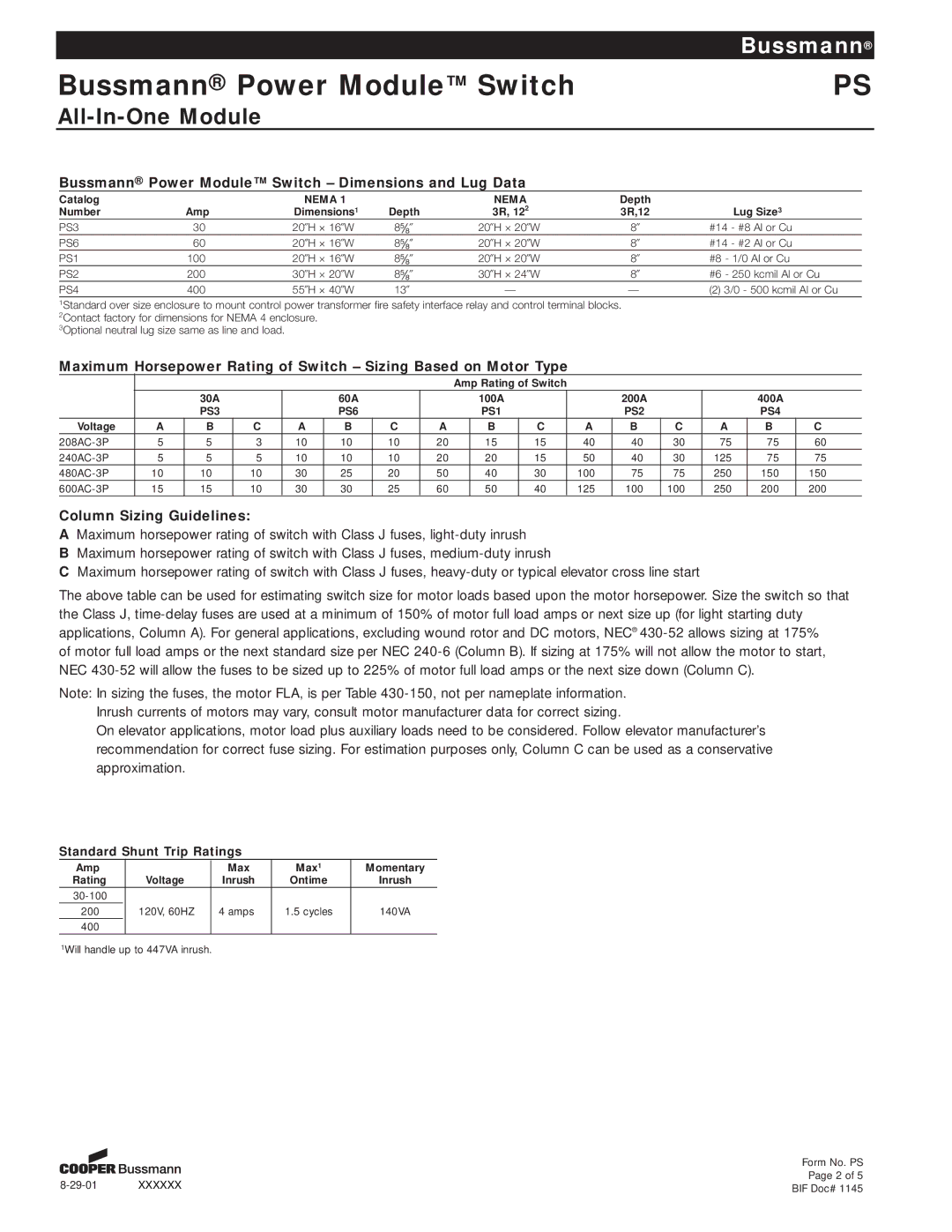
| Bussmann® Power Module™ Switch – Dimensions and Lug Data |
|
|
|
|
|
|
|
|
|
| |||||||||||
| Catalog |
|
|
|
| NEMA 1 |
|
|
| NEMA |
|
|
| Depth |
|
|
|
|
|
| ||
| Number |
| Amp |
|
| Dimensions1 | Depth |
|
| 3R, 122 |
|
|
| 3R,12 |
|
| Lug Size3 |
|
| |||
| PS3 |
| 30 |
|
| 20·H Å 16·W | 8Þ½¥· |
|
| 20·H Å 20·W |
| 8· |
| #14 - #8 Al or Cu |
|
| ||||||
| PS6 |
| 60 |
|
| 20·H Å 16·W | 8Þ½¥· |
|
| 20·H Å 20·W |
| 8· |
| #14 - #2 Al or Cu |
|
| ||||||
| PS1 |
| 100 |
|
| 20·H Å 16·W | 8Þ½¥· |
|
| 20·H Å 20·W |
| 8· |
| #8 - 1/0 Al or Cu |
|
| ||||||
| PS2 |
| 200 |
|
| 30·H Å 20·W | 8Þ½¥· |
|
| 30·H Å 24·W |
| 8· |
| #6 - 250 kcmil Al or Cu |
| |||||||
| PS4 |
| 400 |
|
| 55·H Å 40·W | 13· |
| Ñ |
|
|
|
| Ñ |
| (2) 3/0 - 500 kcmil Al or Cu | ||||||
| 1Standard over size enclosure to mount control power transformer fire safety interface relay and control terminal blocks. |
|
|
|
|
|
| |||||||||||||||
| 2Contact factory for dimensions for NEMA 4 enclosure. |
|
|
|
|
|
|
|
|
|
|
|
|
|
|
|
| |||||
| 3Optional neutral lug size same as line and load. |
|
|
|
|
|
|
|
|
|
|
|
|
|
|
|
|
| ||||
| Maximum Horsepower Rating of Switch – Sizing Based on Motor Type |
|
|
|
|
|
|
|
| |||||||||||||
|
|
|
|
|
|
|
|
|
| Amp Rating of Switch |
|
|
|
|
|
|
|
| ||||
|
|
| 30A |
|
|
| 60A |
|
|
| 100A |
|
|
| 200A |
|
|
| 400A |
|
| |
|
|
| PS3 |
|
|
| PS6 |
|
|
| PS1 |
|
|
| PS2 |
|
|
| PS4 |
|
| |
| Voltage | A | B | C |
| A | B | C | A |
| B |
| C |
| A | B | C | A |
| B | C | |
| 5 | 5 | 3 |
| 10 | 10 | 10 | 20 |
| 15 |
| 15 |
| 40 | 40 | 30 | 75 |
| 75 | 60 |
| |
| 5 | 5 | 5 |
| 10 | 10 | 10 | 20 |
| 20 |
| 15 |
| 50 | 40 | 30 | 125 |
| 75 | 75 |
| |
| 10 | 10 | 10 |
| 30 | 25 | 20 | 50 |
| 40 |
| 30 |
| 100 | 75 | 75 | 250 |
| 150 | 150 |
| |
| 15 | 15 | 10 |
| 30 | 30 | 25 | 60 |
| 50 |
| 40 |
| 125 | 100 | 100 | 250 |
| 200 | 200 |
| |
Column Sizing Guidelines:
AMaximum horsepower rating of switch with Class J fuses,
BMaximum horsepower rating of switch with Class J fuses,
CMaximum horsepower rating of switch with Class J fuses,
The above table can be used for estimating switch size for motor loads based upon the motor horsepower. Size the switch so that the Class J,
of motor full load amps or the next standard size per NEC
Note: In sizing the fuses, the motor FLA, is per Table
On elevator applications, motor load plus auxiliary loads need to be considered. Follow elevator manufacturer’s recommendation for correct fuse sizing. For estimation purposes only, Column C can be used as a conservative approximation.
Standard Shunt Trip Ratings
Amp |
|
| Max | Max1 | Momentary |
Rating |
| Voltage | Inrush | Ontime | Inrush |
|
|
|
|
| |
200 |
| 120V, 60HZ | 4 amps | 1.5 cycles | 140VA |
400 |
|
|
|
|
|
1Will handle up to 447VA inrush.
|
| Form No. PS |
XXXXXX | Page 2 of 5 | |
BIF Doc# 1145 |