| Bussmann® |
Bussmann® Power Module™ Switch | PS |
|
|
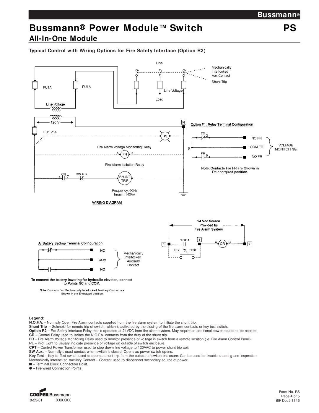
Typical Control with Wiring Options for Fire Safety Interface (Option R2)
Legend:
N.O.F.A. – Normally Open Fire Alarm contacts supplied from the fire alarm system to initiate the shunt trip.
Shunt Trip – Solenoid for remote trip of switch, which is activated by the closing of the fire alarm contacts or key test switch.
Option R2 – Fire Safety Interface Relay that is operated at 24VDC from fire alarm system. May require an additional power source to be needed. CR – Control Relay used to isolate the N.O.F.A. contacts from the duty of the shunt trip.
FR – Fire Alarm Voltage Monitoring Relay used to monitor presence of voltage in switch from a remote location (i.e. Fire Alarm Control Panel). PL – Pilot Light to visually indicate presence of voltage on outside of switch enclosure.
CPT – Control Power Transformer used to step down line voltage to 120VAC to power shunt trip coil. SW Aux. – Normally closed contact when switch is closed. Opens as power switch opens.
Key Test –
■– Terminal Block Connection Point. ● –
Form No. PS
Page 4 of 5
BIF Doc# 1145