COMPRESSOR
1 | 3 | M | C |
115/1/60 |
|
| OVERLOAD |
5 |
| 1 | |
|
|
8 9 M
![]() 6
6
PUMP FAN 115V 24V
| 7 |
|
4 | M |
|
|
| S |
|
| R |
M COMPRESSOR |
|
|
| START RELAY | START |
LIGHT, POWER ON | CAPACITOR | |
|
| |
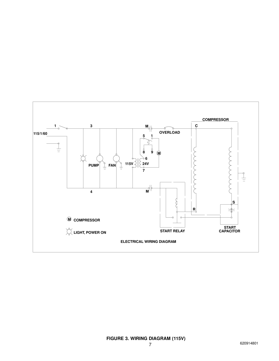
| ELECTRICAL WIRING DIAGRAM |
|
FIGURE 3. WIRING DIAGRAM (115V)
7 | 620914801 |
COMPRESSOR
1 | 3 | M | C |
115/1/60 |
|
| OVERLOAD |
5 |
| 1 | |
|
|
8 9 M
![]() 6
6
PUMP FAN 115V 24V
| 7 |
|
4 | M |
|
|
| S |
|
| R |
M COMPRESSOR |
|
|
| START RELAY | START |
LIGHT, POWER ON | CAPACITOR | |
|
| |
| ELECTRICAL WIRING DIAGRAM |
|
7 | 620914801 |