Step Three
H
H | A |
| |
L.H. Bracket | R.H. Bracket |
P/N 3532 | P/N 3531 |
| 1/16I |
G | G |
| |
| Heat Sink |
| Plates |
Ice Bank Control relative to agitator motor angle.
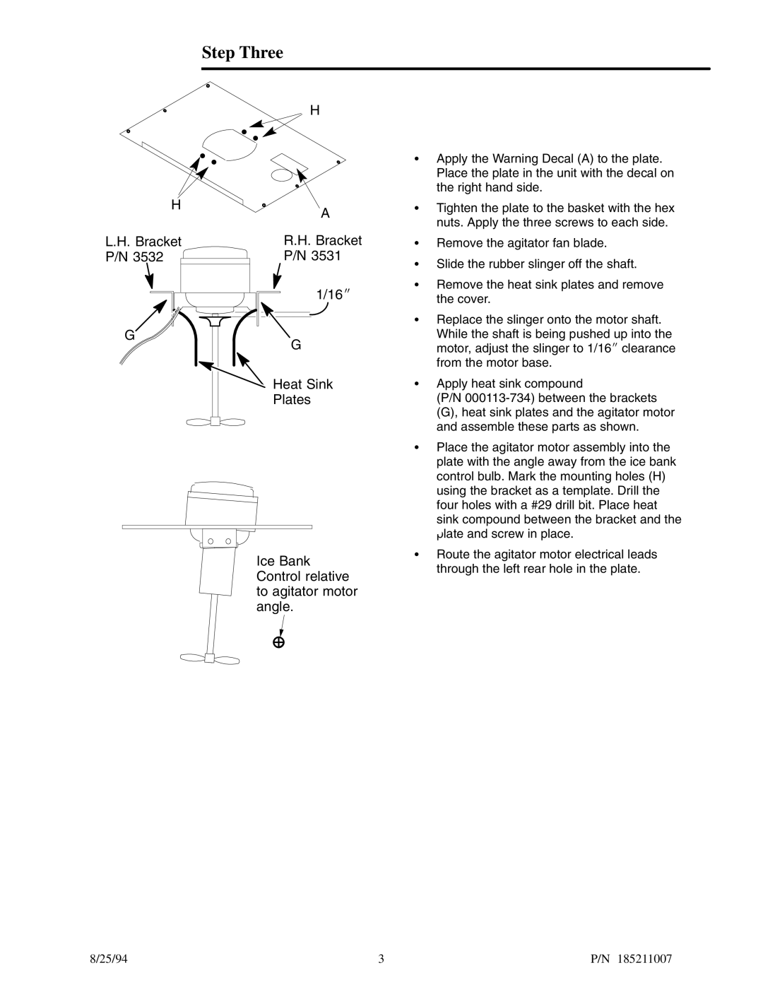
SApply the Warning Decal (A) to the plate. Place the plate in the unit with the decal on the right hand side.
STighten the plate to the basket with the hex nuts. Apply the three screws to each side.
SRemove the agitator fan blade.
SSlide the rubber slinger off the shaft.
SRemove the heat sink plates and remove the cover.
SReplace the slinger onto the motor shaft. While the shaft is being pushed up into the motor, adjust the slinger to 1/16I clearance from the motor base.
SApply heat sink compound
(P/N
SPlace the agitator motor assembly into the plate with the angle away from the ice bank control bulb. Mark the mounting holes (H) using the bracket as a template. Drill the four holes with a #29 drill bit. Place heat sink compound between the bracket and the plate and screw in place.
SRoute the agitator motor electrical leads through the left rear hole in the plate.
8/25/94 | 3 | P/N 185211007 |
