Table 1. Design Data (cont’d)
Water
to | operate on water pressure between 10 PSI and 90 PSI. |
|
|
| |
|
| |
Drain Overflow Line (Located at rear of the Unit) | ||
|
| |
|
| |
Ambient Operating Temperature | 40° F to 100° F | |
|
| |
|
| |
Electrical: |
| |
|
|
|
| Unit Electrical Rating | 115 VAC, 60 Hz, 15.6 Amps, |
|
| Single Phase |
|
|
|
| Recommended Electrical Supply | 115 VAC, 60 hz, 20 Amps |
|
| Dedicated |
|
| Grounded Circuit |
|
| SPECIFICATION CHART |
|
|
|
|
| ||||||
Models | Condensing | VAC |
| HZ | PH | Wire | Comp. | Fan | GRMTR | Refrigerant | Circuit | ||
| Unit |
|
|
|
|
|
| RLA | Amps | Amps | Oz. | Type | Fuse |
Air Cooled | 115 |
| 60 | 1 | 2 |
| 12 | 1.6 | 2 | 24 | R404A | 20 | |
Water Cooled | 115 |
| 60 | 1 | 2 |
| 12 | N/A | 2 | 13 | R404A | 20 | |
|
|
|
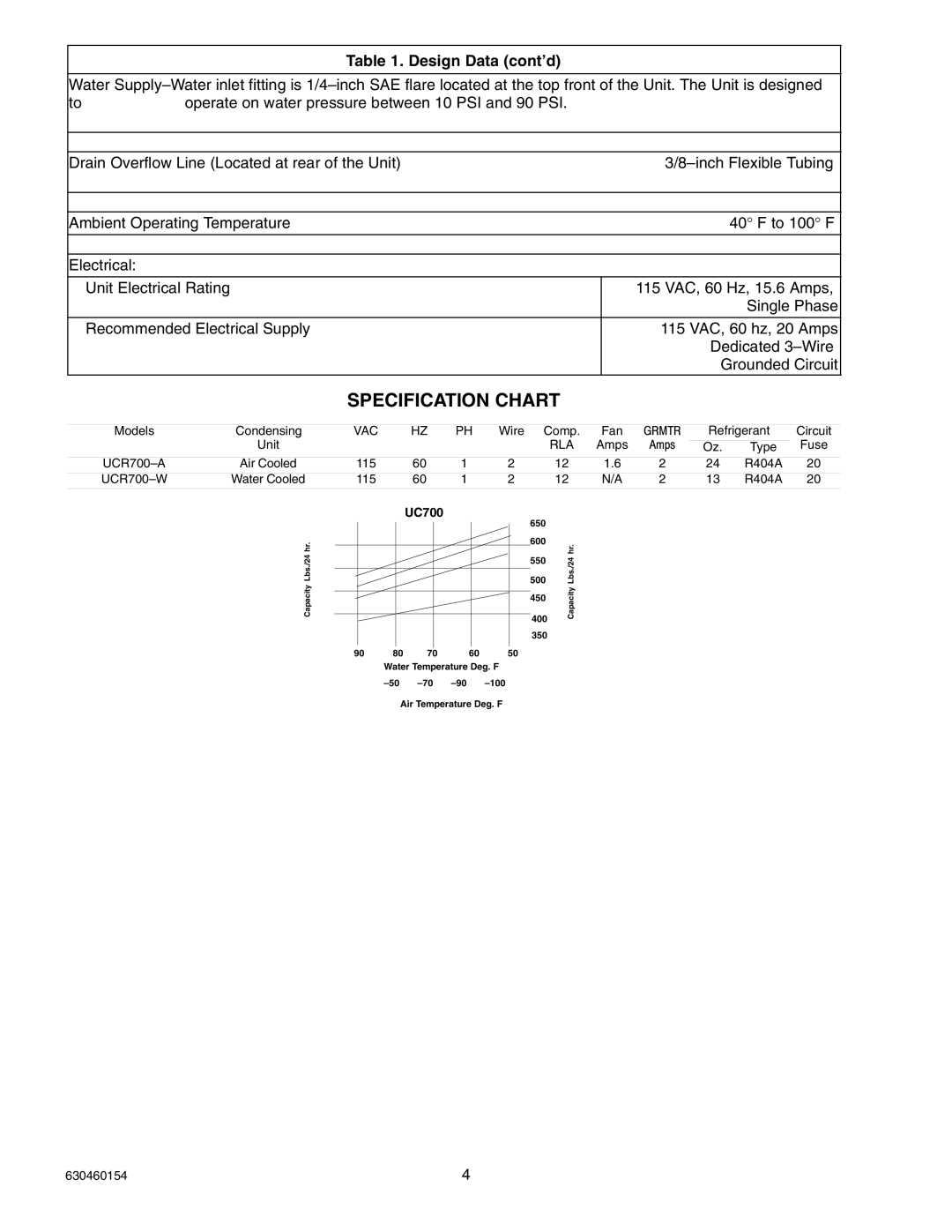
| UC700 |
|
| 650 |
|
|
|
|
|
|
|
|
|
|
|
|
|
|
|
|
|
|
| |
| hr. |
|
|
|
|
| 600 | hr. |
|
|
|
|
|
|
|
|
|
|
| 500 |
|
|
|
|
| ||
| Lbs./24 |
|
|
|
|
| Lbs./24 |
|
|
|
|
| |
|
|
|
|
|
|
| 550 |
|
|
|
|
|
|
| Capacity |
|
|
|
|
| 450 | Capacity |
|
|
|
|
|
|
|
|
|
|
|
|
|
|
|
|
|
| |
|
|
|
|
|
|
| 400 |
|
|
|
|
|
|
|
|
|
|
|
|
| 350 |
|
|
|
|
|
|
|
| 90 | 80 | 70 | 60 | 50 |
|
|
|
|
|
|
|
|
|
| Water Temperature Deg. F |
|
|
|
|
|
|
| |||
|
|
|
|
|
|
|
|
|
| ||||
|
|
| Air Temperature Deg. F |
|
|
|
|
|
|
| |||
630460154 | 4 |