SERVICE AND MAINTENANCE
Move the remote chute lever on the control panel forward to pivot the upper chute down; move the lever rearward to pivot the upper chute up.
Wheel drive control
Refer to the Adjustment section of the Assembly instructions to adjust the wheel drive control. To further check the adjustment, proceed as follows:
1.With the snow thrower tipped forward (be certain to run the fuel tank dry before tipping the unit forward), remove the frame cover underneath the snow thrower by removing the
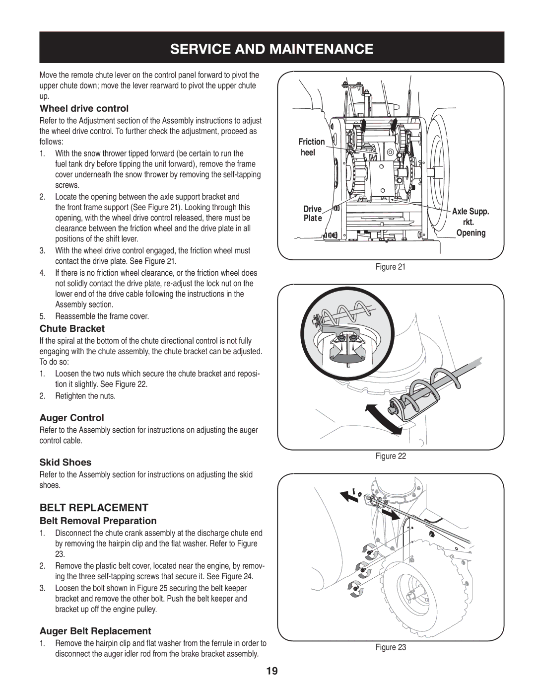
2.Locate the opening between the axle support bracket and the front frame support (See Figure 21). Looking through this opening, with the wheel drive control released, there must be clearance between the friction wheel and the drive plate in all positions of the shift lever.
3.With the wheel drive control engaged, the friction wheel must contact the drive plate. See Figure 21.
4.If there is no friction wheel clearance, or the friction wheel does not solidly contact the drive plate,
5.Reassemble the frame cover.
Chute Bracket
If the spiral at the bottom of the chute directional control is not fully engaging with the chute assembly, the chute bracket can be adjusted. To do so:
1.Loosen the two nuts which secure the chute bracket and reposi- tion it slightly. See Figure 22.
2.Retighten the nuts.
Auger Control
Refer to the Assembly section for instructions on adjusting the auger control cable.
Skid Shoes
Refer to the Assembly section for instructions on adjusting the skid shoes.
Belt replacement
Belt Removal Preparation
1.Disconnect the chute crank assembly at the discharge chute end by removing the hairpin clip and the flat washer. Refer to Figure 23.
2.Remove the plastic belt cover, located near the engine, by remov- ing the three
3.Loosen the bolt shown in Figure 25 securing the belt keeper bracket and remove the other bolt. Push the belt keeper and bracket up off the engine pulley.
Auger Belt Replacement
1.Remove the hairpin clip and flat washer from the ferrule in order to disconnect the auger idler rod from the brake bracket assembly.
Friction
Wheel ![]()
Drive
Plate
Figure 21
Figure 22
Figure 23
Axle Supp.
Brkt.
Opening
19