ASSEMBLY
NOTE: References to right or left side of the snow thrower are determined from behind the unit in the operating position (standing directly behind the snow thrower, facing the handle panel).
Removing From Crate
1.Remove screws from the bottom of the crate securing the sides, and ends of the shipping crate.
2.Lift off the top off of the crate and set out of the way of the assembly area.
3.Remove and discard plastic bag that covers unit.
4.Remove any loose parts included with unit (e.g., Operator’s Manual, etc.).
5.Push down on the lower handle and pull unit back out of crate.
6.Make certain the crate has been completely emptied before discarding it.
assembly
1.Make certain the springs at the lower end of the auger and drive cables are securely hooked into their respective actuator bracket before pivoting the handle upward. Refer to Fig. 10.
a.Place the shift lever in the F6 position.
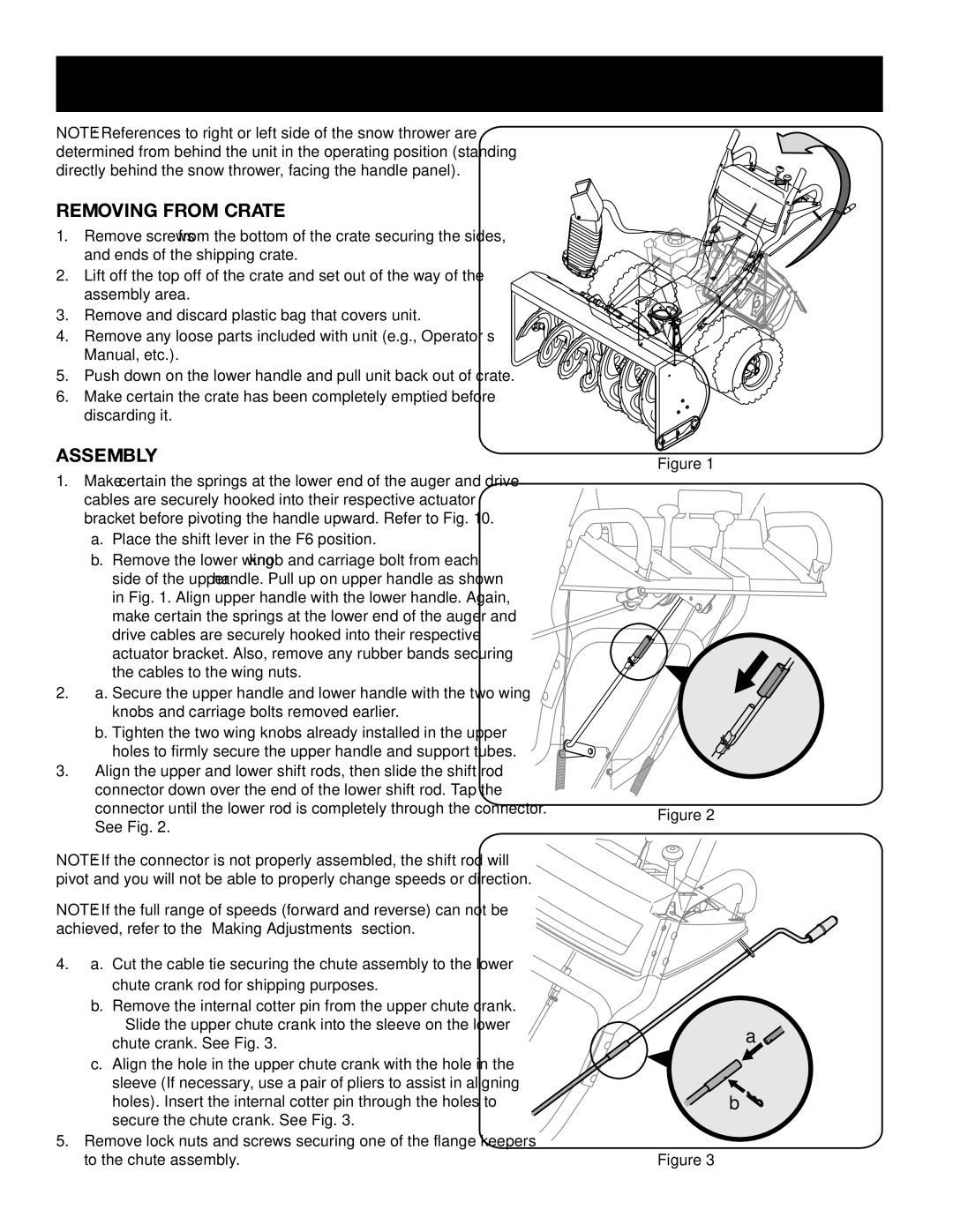
b.Remove the lower wing knob and carriage bolt from each side of the upper handle. Pull up on upper handle as shown in Fig. 1. Align upper handle with the lower handle. Again, make certain the springs at the lower end of the auger and drive cables are securely hooked into their respective actuator bracket. Also, remove any rubber bands securing the cables to the wing nuts.
2.a. Secure the upper handle and lower handle with the two wing knobs and carriage bolts removed earlier.
b.Tighten the two wing knobs already installed in the upper holes to firmly secure the upper handle and support tubes.
3.Align the upper and lower shift rods, then slide the shift rod connector down over the end of the lower shift rod. Tap the connector until the lower rod is completely through the connector. See Fig. 2.
NOTE: If the connector is not properly assembled, the shift rod will pivot and you will not be able to properly change speeds or direction.
NOTE: If the full range of speeds (forward and reverse) can not be achieved, refer to the “Making Adjustments” section.
4.a. Cut the cable tie securing the chute assembly to the lower chute crank rod for shipping purposes.
b.Remove the internal cotter pin from the upper chute crank. Slide the upper chute crank into the sleeve on the lower chute crank. See Fig. 3.
c.Align the hole in the upper chute crank with the hole in the sleeve (If necessary, use a pair of pliers to assist in aligning holes). Insert the internal cotter pin through the holes to secure the chute crank. See Fig. 3.
5.Remove lock nuts and screws securing one of the flange keepers to the chute assembly.
Figure 1
Figure 2
a ![]()
b ![]()
Figure 3
8