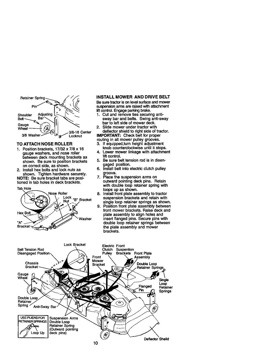
TOATTACHNOSEROLLER
1.Positionbrackets,17/32x7/8x16
gaugewashers,andnoseroller betweendeckmountingbracketsas shownBesuretopositionbrackets. oncorrectside,as shown.
2.Install hex bolts and look nuts as
shown. Tighten hardware securely. NOTE: Be sure bracket tabs are posi- tioned in tab holes in deck brackets.
TabHole |
|
|
| _Nose | Roller |
(i'_ | ._'_ | Lock , . |
Nut B Bracket |
•Was,ar
INSTALL MOWER AND DRIVE BELT
Be sure tractoris on leve_surfaceand mower
su_ arms are _ with attachment liftcontrol.Engage parkingbrake.
1.Cut and remove ties securing anti- sway bar and belts. Swing
2.Slide mower under tractor with
deflector shield to fight side of tractor. IMPORTANT: Check belt for proper routing in all mower pulley grooves.
3.If equipped,turn height adjustment knob counterclockwise until it stops.
4.Lower mower linkage with attachment lift control.
5.Be sure belt tension rod is in disen- gaged position.
6.Install belt into electric clutch pulley groove.
7.Place the suspension arms on outward pointing deck pins. Retain with double loop retainer spring with loops up as shown.
8.Install front plate assembly to tractor suspension brackets and retain with single loop retainer springs as shown.
9.Position front plate assembly between front mower brackets. Raise deck and plate assembly to align holes and insert flanged pins. Secure pins with double loop retainer springs between
the plate assembly and mower brackets.
Lock Bracket | Electric | Front |
Belt Tension Rod | Clutch | Suspention |
| Pulley | Brackets Front Plate |
| Front |
Chassis | Mower |
Bracket _ |
Gauge
Wheel
|
|
| Single |
|
|
| Loop |
|
|
| Retainer |
|
|
| Spdngs |
Double |
|
|
|
Sprin |
| ||
USEPUERSFOR | Suspension | Arms | |
RETAINER SPRINGS Doub e Loop | |||
j_ |
| Retainer Spdng | |
//_F. | \ | (Outward | pointing |
,_ j | Loop Up | deck pins) | Deflector Sheild |
|
|
| |
10