CARTONCONTENTS | 5. Before using | the unit, tighten the |
Checkcartoncontentsagainstthefol- | knob securely | by turning clock- |
lowinglist. | wise. |
|
Model0944.511591 |
|
|
• Brushcutterattachment | Coupler | Pnmary Hole |
• Handlebar | "\ | / Guide Recess |
| ||
• Handlebarmountingbracketfor1" |
|
|
(2.5cm)shaft |
|
|
• Handlebarmountingbracketfor7/8" | !er oe ino | |
(2.2cm)shaft | ||
• Bracketcover(2) | SP_ff | RBe_ttase AttL°_erent |
• Shoulderstrap |
|
|
• Uppershoulderstrapclamp | ,ram,WARNING: | Make sure the lock- |
• Lowershoulderstrapclamp(with | ||
| £k |
|
spacertabs)
• Handlebarbracketscrews(4) ing/release button is locked in the pri-
•Shoulderstrapclampscrews(2) mary hole and the knob is securely
•AttachmentHangertightened before operating the unit.
•HexWrenchASSEMBLYHANDLEBAR
ExaminepartsfordamageDonotuse. | _lJ DANGER: | RISK OF CUT. To avoid | |||||||||
damagedparts. |
|
|
|
|
|
|
| ||||
NOTE:Ifyouneedassistanceorfind | serious injury, the barrier portion | of the | |||||||||
thatpartsaremissingordamaged,con- | handlebar | must | be | installed | as shown | ||||||
tactyourSearsServiceCentre. | on the upper shaft | of the powerbead to | |||||||||
ASSEMBLY |
| provide a barrier between operator and | |||||||||
| the spinning blade. Attach | handlebar | |||||||||
|
|
|
|
| mounting bracket above arrow on | ||||||
| WARNING:Ifreceivedassembled, |
|
|
|
|
| |||||
repeatallstepstoensureyourunitis | safety warning decal on the upper | ||||||||||
shaft (powerhead | end of unit). |
| |||||||||
properlyassembledandallfasteners | Ensure handlebar | is positioned | on | ||||||||
aresecure. |
|
| mounting | bracket | at the end of the ar- | ||||||
• Ahexwrench(provided)isrequiredrow on the handlebar decal. |
| ||||||||||
forassembly. |
| NOTE: Two mounting brackets are in- | |||||||||
INSTALLINGBRUSHCUTTER | AT- | ||||||||||
cluded with this | attachment. | Both brack- | |||||||||
TACHMENT |
|
|
| ets are provided to adapt this attach- | |||||||
CAUTION: | When removing | or instal- | |||||||||
ment for use with powerheads that have | |||||||||||
ling attachments, place the unit on a | |||||||||||
either a 1" | (2.5 | cm) diameter or | a 7/8" | ||||||||
flat | surface | for | stability. |
| |||||||
| (2.2 cm) diameter upper shaft. The cor- | ||||||||||
1. | Loosen | the | coupler by turning the | rect bracket must be used to ensure that | |||||||
| knob counterclockwise= |
| the handlebar is mounted securely to | ||||||||
|
|
|
|
| |||||||
|
|
|
|
| the upper shaft before use. |
|
| ||||
| Coupler |
|
|
|
|
|
|
|
| ||
|
|
| _OOSEN | Handlebar | _ | _ | Screw | ||||
|
|
|
|
|
|
|
|
| |||
TIGHTEN | Knob | ou2tito |
|
| |
2. Remove the shaft | cap from the | J |
brushcutter attachment (if present). |
| |
3.Position locking/release button of attachment into guide recess of coupler.
4.Push the attachment into the cou-
pler until the locking/release button snaps into the primary hole.
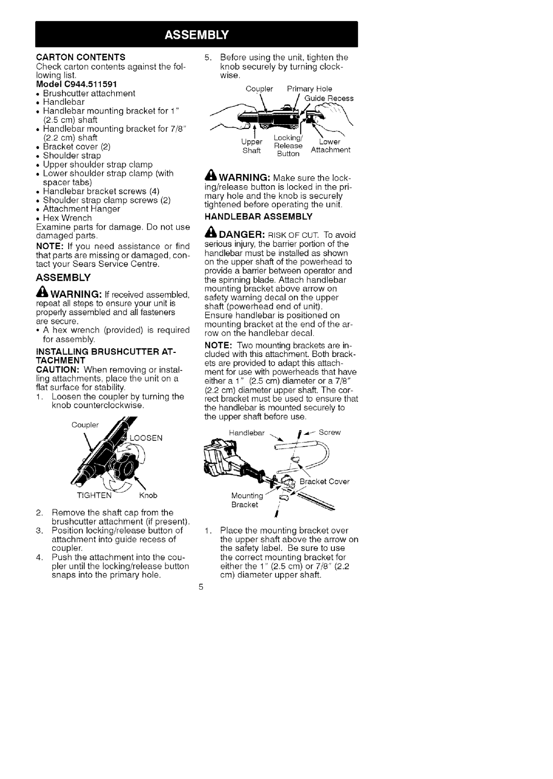
Place the mounting bracket over the upper shaft above the arrow on the safety label. Be sure to use the correct mounting bracket for either the 1" (2.5 cm) or 7/8" (2.2 cm) diameter upper shaft.
